AMC 27.1302 Installed
systems and equipment for use by the crew members
ED
Decision 2021/010/R
1) INTRODUCTION
1.1 Background
Demonstrating compliance with the design requirements that relate to
human abilities and limitations is subject to interpretation. Findings may
vary depending on the novelty, complexity or integration of the system design.
EASA considers that describing a structured approach to selecting and
developing acceptable means of compliance is useful in supporting the standardisation
of compliance demonstration practices.
(a) This acceptable means of compliance
(AMC) provides the means for demonstrating compliance with CS 27.1302 and complements the means of compliance (MoC) for several other paragraphs
in CS-27(refer to paragraph 2, Table 1 of this AMC) that relate to
the installed systems and equipment used by the crew members for the operation
of a rotorcraft. In particular, this AMC addresses the design and approval of
installed systems and equipment intended for use by the crew members from
their normal seating positions in the cockpit, or their normal operating
positions in the cabin.
(b) This AMC applies to crew member
interfaces and system behaviour for all the installed systems and equipment
used by the crew members in the cockpit and the cabin while operating the rotorcraft
in normal, abnormal/malfunction and emergency conditions. The functions of the
crew members that operate from the cabin need to be considered in case they
may interfere with the ones under the responsibility of the cockpit crew, or in
case dedicated certification specifications are included in CS-27.
(c) This AMC does not apply
to crew member training, qualification or licensing requirements.
(d) EASA recognises that when Part 21 requires
27.1302 to be part of the certification basis, the amount of effort the
applicant has to make for demonstrating compliance with it may vary and not
all the material contained within this AMC should be systematically followed.
A proportionate approach is embedded within the AMC and is described in
paragraph 3.2.9. The proportionate approach affects the demonstration of
compliance and depends on criteria such as the rotorcraft category (A or B), the
type of operation (VFR, IFR), and the classification of the change.
For the
purposes of this AMC, the following definitions apply:
—
alert: a cockpit
indication that is meant to attract the attention of the crew, and identify to
them an operational or aircraft system condition. Warnings, cautions, and advisories
are considered alerts.
—
assessment: the
process of finding and interpreting evidence to be used by the applicant in
order to establish compliance with a specification. For the purposes of this
AMC, the term ‘assessment’ may refer to both evaluations and tests.
Evaluations are intended to be conducted using partially representative test
means, whereas tests make use of conformed test articles.
—
automation: the
technique of controlling an apparatus, a process or a system by means of electronic
and/or mechanical devices, which replaces the human organism in the sensing, decision-making
and deliberate output.
—
cabin: the
area of the aircraft, excluding the cockpit, where the crew members can
operate the rotorcraft systems; for the purposes of this AMC, the scope of the
cabin is limited to the areas used by the crew members to operate:
—
the systems that share controls and
information with the cockpit;
—
the systems which have controls and
information with similar direct or indirect consequences other than the
one in the cockpit (e.g. precision hovering).
—
catachresis: applied
to the area of tools, ‘catachresis’ means the use of a tool for a function other
than the one planned by the designer of the tool; for instance, the use of a
circuit breaker as a switch.
—
clutter: an
excessive number and/or variety of symbols, colours, or other information that
may reduce the access to the relevant information, increase interpretation
time and the likelihood of interpretation error.
—
cockpit: the
area of the aircraft where the flight crew members work and where the primary
flight controls are located.
—
conformity: official
verification that the cockpit/system/product conforms to the type design data.
—
cockpit controls:
the interaction with a control means that the crew manipulates in order to
operate, configure, and manage the aircraft or its flight control surfaces,
systems, and other equipment.
This may
include equipment in the cockpit such as:
—
control devices,
—
buttons,
—
switches,
—
knobs,
—
flight controls, and
—
levers.
—
control
device: a
control device is a piece of equipment that allows the crew to interact with the
virtual controls, typically used with the graphical user interface; control
devices may include the following:
—
keyboards,
—
touchscreens,
—
cursor-control devices (keypads,
trackballs, pointing devices),
—
knobs, and
—
voice-activated controls.
—
crew member: a
person that is involved in the operation of the aircraft and its systems; in the
case of rotorcraft, the operator in the cabin that can interfere with the
cockpit-crew tasks (for instance, the operator in the cabin assigned to operate
the rescue hoist or to help the cockpit-crew control the aircraft in a hover is
considered a crew member).
—
cursor-control
device: a control
device for interacting with the virtual controls, typically used with a
graphical user interface on an electro-optical display.
—
design
eye reference point (DERP): a point in the cockpit that provides a finite reference enabling the
precise determination of geometric entities that define the layout of the cockpit.
—
design feature:
a design feature is an attribute or a characteristic of a design.
—
design item: a
design item is a system, an equipment, a function, a component or a design
feature.
—
design philosophy:
a high-level description of the human-centred design principles that guide the
designer and aid in ensuring that a consistent, coherent user interface is
presented to the crew.
—
design-related
human performance issue: a deficiency that results from the interaction between the crew and
the system. It includes human errors, but also encompasses other kinds of
shortcomings such as hesitation, doubt, difficulty in finding information,
suboptimal strategies, inappropriate levels of workload, or any other
observable item that cannot be considered to be a human error, but still
reveals a design-related concern.
—
display: a device
that transmits data or information from the aircraft to the crew.
—
flight crew member:
a licensed crew member charged with duties that are essential for the
operation of an aircraft during a flight duty period.
—
human error: a
deviation from what is considered correct in some context, especially in the
hindsight of the analysis of accidents, incidents, or other events of
interest. Some types of human error may be the following: an inappropriate
action, a difference from what is expected in a procedure, an incorrect
decision, an incorrect keystroke, or an omission. In the context of this AMC,
human error is sometimes referred to as ‘crew error’ or ‘pilot error’.
—
multifunction control:
a control device that can be used for many functions, as opposed to a control
device with a single dedicated function.
—
abnormal/malfunction or emergency conditions: for the purposes of this AMC, abnormal/malfunction
or emergency operating conditions refer to conditions that do require the crew
to apply procedures different from the normal procedures included in the
rotorcraft flight manual (RFM).
—
operationally
relevant behaviour: operationally relevant behaviour is meant to convey
the net effect of the system logic, controls, and displayed information of the
equipment upon the awareness of the crew or their perception of the operation
of the system to the extent necessary for planning actions or operating the
system. The intent is to distinguish such system behaviour from the functional
logic within the system design, much of which the crew does not know or does
not need to know, and which should be transparent to them.
—
system function allocation:
a human factors (HFs) method for deciding whether a particular function will
be accomplished by a person, technology (hardware or software) or some mix of a
person and technology (also referred to as ‘task allocation’).
—
task analysis:
a formal analytical method used to describe the nature and relationships of
complex tasks involving a human operator.
The following is a list of abbreviations used in this AMC:
|
AC |
advisory
circular |
|
AMC |
acceptable
means of compliance |
|
CAM |
cockpit
area microphone |
|
CRM |
crew resource
management |
|
CVR |
cockpit
voice recorder |
|
CS |
certification
specification |
|
DLR |
data
link recorder |
|
DOT |
Department
of Transportation |
|
EASA |
European
Union Aviation Safety Agency |
|
ED |
EUROCAE
Document |
|
FAA FMS GM HFs HMI |
Federal
Aviation Administration flight
management system guidance
material human factors human–machine
interface |
|
ICAO |
International
Civil Aviation Organization |
|
ISO |
International
Standards Organization |
|
LoI MoC PA RFM |
level of
involvement means of
compliance public address rotorcraft
flight manual |
|
SAE |
Society
of Automotive Engineers |
|
STC |
supplemental
type certificate |
|
TAWS |
terrain
awareness and warning system |
|
TCAS |
traffic alert
and collision avoidance system |
|
TSO |
technical
standard order |
|
VOR |
very
high frequency omnidirectional range |
2) RELATION
BETWEEN CS
27.1302 AND OTHER SPECIFICATIONS, AND ASSUMPTIONS
2.1 The relation of CS 27.1302 to other specifications
(a) CS-27
Book 2 establishes that the AMC for CS-27 is the respective FAA AC 27-1
revision adopted by EASA with the changes/additions included within Book 2. AC 27-1
includes the Miscellaneous Guidance MG-20 ‘Human Factors’. MG-20 aims to
assist the applicant in understanding the HFs implications of the CS-27 paragraphs.
In order to achieve this objective, MG-20 provides a list of all CS-27 HFs-related
specifications, including those relevant to the performance and handling
qualities, and helps to address within the certification plan some of the specifications
that deal with the system design with additional guidance. However, MG-20 does
not include specific guidance on how to perform a comprehensive HFs assessment
as required by 27.1302. Therefore, adherence to the guidance material included within AC 27-1
and the associated MG-20 is not sufficient to demonstrate compliance with CS 27.1302.
(b) This
AMC provides dedicated guidance for demonstrating compliance with CS 27.1302. To help the applicant reach the objectives of CS 27.1302, some additional guidance related to other specifications associated
with the installed equipment that the crew members use to operate the rotorcraft
is also provided in Section 4. Table 1 below contains a list of these specifications
related to cockpit design and crew member interfaces for which this AMC
provides additional design guidance. Note that this AMC does not provide a
comprehensive means of compliance for any of the specifications beyond CS 27.1302.
Paragraph 2 — Table 1: Certification
specifications relevant to this AMC
|
CS-27
BOOK 1 references |
General
topic |
Referenced
material in this AMC |
|
CS 27.771(a) |
Unreasonable concentration or fatigue |
Error, 4.5. Integration, 4.6. Controls, 4.2. System behaviour, 4.4. |
|
CS 27.771(b) |
Controllable from either pilot seat |
Controls, 4.2. Integration, 4.6. |
|
|
Pilot compartment view |
Integration, 4.6. |
|
CS 27.777(a) |
Convenient operation of the controls |
Controls, 4.2. Integration, 4.6. |
|
CS 27.777(b) |
Fully and unrestricted movement |
Controls, 4.2. Integration, 4.6. |
|
Motion and effect of cockpit controls |
Controls, 4.2. |
|
|
CS 27.1301(a) |
Intended function of installed systems |
Error, 4.5. Integration, 4.6. Controls, 4.2. Presentation of information, 4.3. System behaviour, 4.4. |
|
Crew error |
Error, 4.5. Integration, 4.6. Controls, 4.2. Presentation of information, 4.3. System behaviour, 4.4. |
|
|
CS 27.1309(a) |
Intended function of required equipment under all operating
conditions |
Controls, 4.2. Integration, 4.6. |
|
Visibility of instruments |
Integration, 4.6. |
|
|
Warning caution and advisory lights |
Integration, 4.6. |
|
|
CS 27.1329 and Appendix B VII |
Automatic pilot system |
System behaviour, 4.4. |
|
Flight director systems |
System behaviour, 4.4 |
|
|
Minimum crew |
Controls, 4.2. Integration, 4.6. |
|
|
CS 27.1543(b) |
Visibility of instrument markings |
Presentation of information, 4.3. |
|
Powerplant instruments |
Presentation of information, 4.3. |
|
|
CS 27.1555(a) |
Control markings |
Controls, 4.2. |
|
Miscellaneous marking and placards |
Presentation of information, 4.3. |
(c) Where
means of compliance in other AMCs are provided for specific equipment and
systems, those means are assumed to take precedence if a conflict exists with the
means provided here.
In order to demonstrate compliance with all
the specifications referenced by this AMC, all the certification activities
should be based on the assumption that the rotorcraft will be operated by qualified
crew members who are trained in the use of the installed systems and equipment.
3) HUMAN FACTORS CERTIFICATION
(a) This paragraph provides an overview of the
human factors (HFs) certification process that is acceptable to demonstrate
compliance with CS 27.1302. This includes a description of the recommended
applicant activities, the communication between the applicant and EASA, and
the expected deliverables.
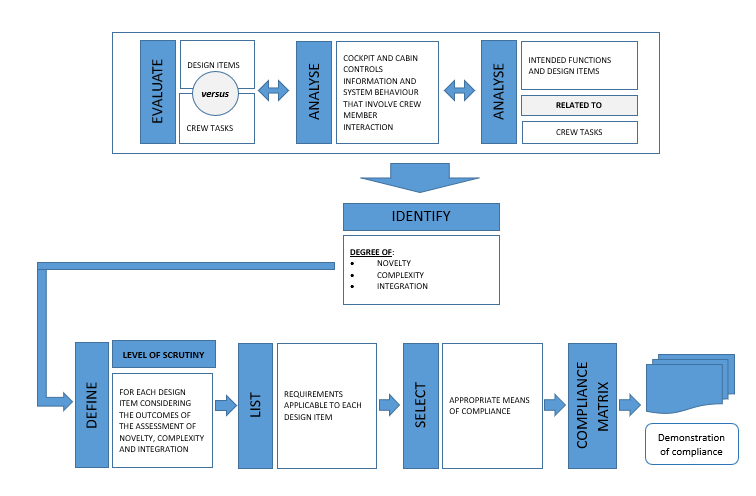
(b) Figure 1 illustrates the main steps in the
HFs certification process.
Paragraph 3 — Figure 1: Methodical approach to the certification for
design‑related human performance issues
3.2 Certification steps and
deliverables
3.2.1 Identification of the cockpit and cabin
controls, information and systems that involve crew member interaction
(a) As an initial step, the applicant should consider
all the design items used by the crew members with the aim of identifying the controls,
information and system behaviour that involve crew member interaction.
(b) In case of a modification, the scope of
the functions to be analysed is limited to the design items affected by the
modification and its integration.
(c) The objective is to analyse and document
the crew member tasks to be performed, or how tasks might be changed or
modified as a result of introducing a new design item(s).
(d) Rotorcraft can be operated in different
environments and types of missions. Therefore, while mapping the cockpit and the
applicable crew member interfaces in the cabin or, in case of modification,
the modified design items versus the crew member tasks and the design item
intended functions, the type of approvals under the type design applicable to
the rotorcraft under assessment should be considered and documented.
For instance,
approvals for:
—
VFR,
—
IFR,
—
NVIS,
—
SAR,
—
aerial work (cargo hook or rescue
hoist), or
—
flight in known icing conditions
require
different equipment to be installed or a different use of the same equipment.
Therefore, the applicant should clarify the assumptions made when the
assessment of the cockpit and the cabin functions is carried out.
3.2.2 The intended function of the equipment and the
associated crew member tasks
(a) CS 27.1301(a) requires that ‘each item of
installed equipment must be of a kind and design appropriate to its intended
function’. CS 27.1302 establishes the requirements
to ensure that the design supports the ability of the crew members to perform the
tasks associated with the intended function of a system. In order to demonstrate
compliance with CS 27.1302, the intended function of a system
and the tasks expected to be performed by the crew members must be known.
(b) An applicant’s statement of the intended
function should be sufficiently specific and detailed so that it is possible
to evaluate whether the system is appropriate for the intended function(s) and
the associated crew member tasks. For example, a statement that a new display
system is intended to ‘enhance situational awareness’ should be further
explained. A wide variety of different displays enhance the situational
awareness in different ways. Some examples are terrain awareness, vertical
profiles, and even the primary flight displays. The applicant may need to
provide more detailed descriptions for designs with greater levels of novelty,
complexity, or integration.
(c) The applicant should describe the intended
function(s) and associated task(s) for:
(1) each design item affected by the
modification and its integration;
(2) crew indications and controls for that
equipment; and
(3) the prominent characteristics of those
indications and controls.
This type of
information is of the level typically provided in a pilot handbook or an
operations manual. It would describe the indications, controls, and crew member
procedures.
(d) The applicant may evaluate whether the statement
of the intended function(s) and the associated task(s) is sufficiently
specific and detailed by using the following questions:
(1) Does each design item have a stated
intent?
(2) Are the crew member tasks associated with
the function(s) described?
(3) What assessments, decisions, and actions
are crew members expected to make based on the information provided by the
system?
(4) What other information is assumed to be
used in combination with the system?
(5) Will the installation or use of the system
interfere with the ability of the crew members to operate other cockpit
systems?
(6) Are any assumptions made about the
operational environment in which the equipment will be used?
(7) What assumptions are made about the attributes
or abilities of the crew members beyond those required in the regulations
governing operations, training, or qualification?
(e) The output of this step is a list of design
items, with each of the associated intended functions that has been related to
the crew member tasks.
3.2.3 Determining the level of scrutiny
(a) The depth and extent of the HFs
investigation to be performed in order to demonstrate compliance with CS 27.1302 is driven by the level of scrutiny.
The level of
scrutiny is determined by analysing the design items using the criteria
described in the following subparagraph:
(1) Integration. The level
of the systems’ integration refers to the extent to which there are interdependencies
between the systems that affect the operation of the rotorcraft by the crew
members. The applicant should describe the integration between systems because
it may affect the means of compliance. Paragraph 4.6 also refers to
integration. In the context of that paragraph, ‘integration’ defines how
specific systems are integrated into the cockpit and how the level of
integration may affect the means of compliance.
(2) Complexity. The level
of complexity of the system design from the crew members’ perspective is an
important factor that may also affect the means of compliance. Complexity has
multiple dimensions, for instance:
—
the number, the accessibility and the level
of integration of information that the crew members have to use (the number of
items of information on a display, the number of colours), alerts, or voice
messages may be an indication of the complexity;
—
the number, the location and the
design of the cockpit controls associated with each system and the logic
associated with each of the controls; and
—
the number of steps required to
perform a task, and the complexity of the workflows.
(3) Novelty. The novelty
of a design item is an important factor that may also affect the means of
compliance. The applicant should characterise the degree of novelty on the basis
of the answers to the following questions:
(i) Are any new functions introduced into the
cockpit design?
(ii) Does the design introduce a new intended
function for an existing or a new design item?
(iii) Are any new technologies introduced that
affect the way the crew members interact with the systems?
(iv) Are any new design items introduced at
aircraft level that affect crew member tasks?
(v) Are any unusual procedures needed as a result
of the introduction of a new design item?
(vi) Does the design introduce a new way for
the crew members to interact with the system?
While
answering the above questions, each negative response should be justified by
the applicant identifying the reference product as well that has been
considered. The reference product can be an avionics suite or an entire flight
deck previously certified by the same applicant.
The degree
of novelty should be proportionate to the number of positive answers to the
above questions.
The level of scrutiny performed by the
applicant should be proportionate to the number of the above criteria which
are met by each design item. Applicants should be aware that the impact of a
complex design item might also be affected by its novelty and the extent of
its integration with other elements of the cockpit. For example, a complex but
not novel design item is likely to require a lower level of scrutiny than one
that is both complex and novel. The applicant is expected to include in the
certification plan all the items that have been analysed with the associated
level of scrutiny.
(c) The applicant may use a simpler approach
for design items that have been assigned a low level of scrutiny.
3.2.4 Determining the level of scrutiny —
EASA’s familiarity with the project
The assessment
of the classifications of the level of scrutiny proposed by the applicant requires
the EASA flight and HFs panels to be familiar with the project, making use of
the available material and tools.
3.2.5 Applicable HFs design
requirements
(a) The applicant should identify the HFs design
requirements applicable to each design item for which compliance must be demonstrated.
This may be accomplished by identifying the design characteristics of the
design items that could adversely affect the performance of the crew members,
or that pertain to the avoidance and management of crew member errors. Specific
design considerations for the requirements that involve human performance are
discussed in paragraph 4.
(b) The expected output of this
step is a compliance matrix that links the design items and the HFs design
requirements that are deemed to be relevant and applicable so that a detailed
assessment objective can be derived from each pair of a design item and a HFs design
requirement. That objective will have then to be verified using the most appropriate
means of compliance, or a combination of means of compliance. GM2 27.1302 provides one possible
example of this matrix.
3.2.6 Selecting
the appropriate means of compliance
(a) The applicant should review paragraph 5.2
for guidance on the selection of the means of compliance, or multiple means of
compliance, appropriate to the design. In general, it is expected that the
level of scrutiny should increase with higher levels of novelty, complexity or
integration of the design. It is also expected that the amount of effort dedicated
to the demonstration of compliance should increase with higher levels of
scrutiny (e.g. by using multiple means of compliance and/or multiple HFs
assessments on the same topic).
(b) The output of this step will consist of
the list of means of compliance that will be used to verify the HFs objectives.
3.2.7 Certification programme
The
applicant should document the certification process, outputs and agreements
described in the previous paragraphs. This may be done in a separate plan or incorporated
into a higher-level certification programme.
(a) A HFs test programme should be produced
for each assessment and should describe the experimental protocol (the number
of scenarios, the number and profiles of the crew members, practical organisation
of the assessment, etc.), the HFs objectives that are meant to be addressed,
the expected crew member behaviour, and the scenarios expected to be run. When
required by the LoI, the HFs test programme should be provided well in advance
to EASA.
(b) A HFs test report should be produced including
at least the following information:
(1) A summary of:
(i) the test vehicle configuration,
(ii) of test vehicle limitations/representativeness,
(iii) the detailed HFs objectives, and
(iv) the HFs test protocol, including the number
of sessions and crew members, type of crews (test or operational pilots from
the applicant, authority pilots, customer pilots), a description of the scenarios,
the organisation of the session (training, briefing, assessment, debriefing), and
the observers;
(2) A description of the data gathered with
the link to the HFs objectives;
(3) In-depth analyses of the observed HFs findings;
(4) Conclusions regarding the related HFs test
objectives; and
(5) A description of the proposed way to
mitigate the HFs findings (by a design modification, improvements in procedures,
and/or training actions).
If EASA has
retained the review of the test report as part of its LoI, then the applicant
should deliver it following every HFs assessment.
3.2.9 Proportional
approach in the compliance demonstration
In order to
determine the certification programme, some alleviations (in terms of
certification strategy and certification deliverables) may be granted by EASA for
compliance demonstration process, according to the criteria below:
(a) New types
(1) An applicant that seeks an approval for a
CS-27 rotorcraft for IFR or CAT A operations, should follow this AMC in its
entirety.
(2) An applicants that seeks an approval for a
CS-27 rotorcraft only for CAT B and VFR operations, may take advantage of the
alleviations listed in (b)(2) below.
In
particular, the alleviations listed in (b)(2) are expected to be fully
recognised if at least one of the following conditions is met:
(i) the rotorcraft is single engined;
(II) the rotorcraft design to be approved is
not compatible with a future approval for IFR operations.
(b) Significant and non-significant changes
(1) An applicant for a significant change
should follow the criteria established in (a)(1) or (a)(2) above, depending on
the case.
(2) An applicant for a non-significant change
(refer to the change classification in point 21.A.101 of Part 21 and the
related GM):
(i) is not required to develop a dedicated
HFs test programme;
(ii) is allowed to use a single occurrence of a
test for compliance demonstration;
(iii) is allowed to use a single crew to
demonstrate the HFs-scenario-based assessments.
3.3 Certification strategy and
methodologies
(a) The HFs assessment should follow an
iterative process. Consequently, where appropriate, there may be several
iterations of the same system-specific assessment allowing the applicant to
reassess the system if the previous campaigns resulted in design
modifications.
(b) A HFs certification strategy based only on
one assessment, aiming to demonstrate that the design assumptions are valid, is
generally not sufficient (i.e. one final exercise proposed for compliance
demonstration at the very end of the process).
(c) In order to allow a sufficient amount of
design and assessment iterations, it is suggested that the applicant initiate
the certification process as early as possible starting from the early
development phase. The certification process could include familiarisation
sessions that would allow EASA to become familiar with the proposed design,
but also participate in assessments that would possibly allow early credits to
be granted. Potential issues may be identified early on by using this
approach, thus reducing the risk of a late redesign of design items that may
not be acceptable to EASA. Both parties may have an interest in authority
early involvement, as the authority is continuously gaining experience and
confidence in the HFs process and the compliance of the cockpit design. The
representativeness of the systems and of the simulation means in the early
stages of the development is not a key driver, and will not prevent EASA’s
involvement as long as the representativeness issues do not compromise the
validity of the data to be collected.
(d) If an applicant plans to use data provided
by a supplier for compliance demonstration, the approach and the criteria for
accepting that data will have to be shared and agreed with EASA as part of the
HFs certification plan.
3.3.2 Methodogical considerations applicable to HFs
assessments
Various
means of compliance may be selected, as described in paragraph 5.
For the
highest level of scrutiny, the ‘scenario-based’ approach is likely to be the
most appropriate methodology for some means of compliance.
The purpose
of the following points is to provide guidelines on how to implement the
scenario-based approach.
(a) The scenario-based approach is intended to
substantiate the compliance of human–machine interfaces (HMIs). It is based on
a methodology that involves a sample of various crews that are representative
of the future users, being exposed to real operational conditions in a test bench
or a simulator, or in the rotorcraft. The scenarios are designed to show
compliance with selected rules and to identify any potential deviations
between the expected behaviour of the crew members and the activities of the
crew members that are actually observed. The scenario designers can make use
of triggering events or conditions (e.g. a system failure, an ATC request,
weather conditions, etc.) in order to build operational situations that are
likely to trigger observable crew member errors, difficulties or
misunderstandings. The scenarios need to be well consolidated before the test campaign
begins. A dry-run session should be performed by the applicant before any HFs
campaign in order to validate the operational relevance of the scenarios. This
approach should be used for both system- and rotorcraft‑level assessments.
(b) System-level assessments focus on a
specific design item and are intended for an in-depth assessment of the related
functional and operational aspects, including all the operational procedures.
The representativeness of the test article is to be evaluated taking into
account the scope of the assessment. Rotorcraft-level assessments consider the
scope of the full cockpit, and focus on integration and interdependence
issues.
(c) The scenarios are expected to cover a
subset of the detailed HFs test objectives. The link between each scenario and
the test objectives should be substantiated. This rationale should be
described in the certification test plan or in any other relevant document.
(e) Due to interindividual variability, HFs scenario-based
assessments performed with a single crew member are not acceptable. The
usually accepted number of different crew members used for a given campaign
varies from three to five, including the authority crew, if applicable. In the
case of a crew of two with HFs objectives focused on the duties of only one of
the crew members, it is fully acceptable for the applicant to use the same pilot
flying or monitoring (the one who is not expected to produce any HFs data) throughout
the campaign.
(f) In addition to the test report, and in
order to reduce the certification risk, it is recommended that the preliminary
analyses resulting from recorded observations and comments should be presented
by the applicant to EASA soon after the simulator/flight sessions in order to
allow expert discussions to take place.
(g) An initial briefing should be given to the
crew members at the beginning of each session to present the following general
information:
(1) A detailed schedule describing the type
and duration of the activities (the duration of the session, the organisation
of briefing and debriefings, breaks, etc.);
(2) What is expected from the crew members: it
has to be clearly mentioned that the purpose of the assessment is to assess the
design of the cockpit, not the performance of the pilot;
(3) The policy for simulator occupancy: how
many people should be in the simulator versus the number of people in the
control room, and who they should be; and
(4) The roles of the crew members: if crew
members from the applicant participate in the assessment, they should be made
aware that their role differs significantly from their typical expert pilot
role in the development process. For the process to be valid without
significant bias, they are expected to react and behave in the cockpit as
standard operational pilots.
(5) However, the crew members that participate
in the assessment should not be:
(i) briefed in advance about the details of the
failures and events to be simulated; this is to avoid an obvious risk of
experimental bias; nor
(ii) asked before the assessment for their opinion
about the scenarios to be flown.
(h) The crew members need to be properly
trained prior to every assessment so that during the analysis, the ‘lack of
training’ factor can be excluded to the maximum extent possible from the set
of potential causes of any observed design-related human performance issue.
Furthermore, for operational representativeness purposes, realistic crew
member task sharing, from normal to emergency workflows and checklists, should
be respected during HFs assessments. The applicant should make available any
draft or final RFM, procedures and checklists sufficiently in advance for the crew
members to prepare.
(i) When using simulation, the immersion
feeling of the crew should be maximised in order to increase the validity of
the data. This generally leads to recommendations about a sterile environment
(with no outside noise or visual perturbation), no intervention by observers,
no interruptions in the scenarios unless required by the nature of the
objectives, realistic simulation of ATC communications, pilots wearing
headsets, etc.
(j) The method used to collect HFs data needs
to take into account the following principles:
(1) Principles applicable to the collection of
HFs-related data
(i) In order to substantiate compliance with CS 27.1302, it is necessary to collect both
objective and related subjective data.
(A) Objective data on
crew member performance and behaviour should be collected through direct
observation. The observables should not be limited to human errors, but should
also include pilot verbalisations in addition to behavioural indicators such
as hesitation, suboptimal or unexpected strategies, catachresis, etc.
(B) Subjective data
should be collected during the debriefing by the observer through an
interactive dialogue with the observed crew members. The debriefing should be
led using a neutral and critical positioning from the observer. This
subjective data is typically data that cannot be directly observed (e.g. pilot
intention, pilot reasoning, etc.) and facilitate better understanding of the
observed objective data from (i).
(ii) Other tools such as questionnaires and
rating scales could be used as complementary means. However, it is never
sufficient to rely solely on self-administered questionnaires due to the fact
that crew members are not necessarily aware of all their errors, or of
deviations with respect to the intended use.
(2) The HFs assessment should be
systematically video recorded (both ambient camera and displays). Records may
be used by the applicant as a complementary observation means, and by the
authority for verification purposes, when required.
(3) It is very important to conduct debriefings
after the HFs assessments. They allow the applicant’s HFs observers to gather
all the necessary data that has to be used in the subsequent HFs analyses.
(4) HFs observers should respect the best
practices with regard to observation and debriefing techniques.
(5) Debriefings should be based on
non-directive or semidirective interviewing techniques and should avoid the
experimental biases that are well described in the literature in the field of
social sciences (e.g. the expected answer contained in the question,
non-neutral attitude of the interviewer, etc.).
(k) If HFs-related concerns are raised that
are not directly related to the objective of the assessment, they should
nevertheless be recorded, adequately investigated and analysed in the test
report.
(l) Every design-related human performance
issue observed or reported by the crew members should be analysed following
the assessment. In the case of a human error, the analysis should provide
information about at least the following:
(1) The type of error;
(2) The observed operational consequences, and
any reductions in the safety margins;
(3) The description of the operational context
at the time of observation;
(4) Was the error detected? By whom, when and
how?
(5) Was the error recovered? By whom, when and
how?
(6) Existing means of mitigation;
(7) Possible effects of the representativeness
of the test means on the validity of the data; and
(8) The possible causes of the error.
(m) The analysis of design-related human
performance issues has to be concluded by detailing the appropriate way
forward, which is one of the following:
(1) No action required;
(2) An operational recommendation (for a procedural
improvement or a training action);
(3) A recommendation for a design improvement;
or
(4) A combination of items (2) and (3).
(n) Workload assessment is considered and
addressed in different ways through several requirements within CS-27.
(1) The intent of CS
27.1523 is to
evaluate the workload with the objective of demonstrating compliance with the
minimum flight crew requirements.
(2) The intent of CS 27.1302 is to identify
design-related human performance issues.
(3) As per CS 27.1302, the acceptability of workload
levels is one parameter among many to be investigated in order to highlight
potential usability problems. The CS 27.1302 evaluations should not be
limited to the workload alone. Workload ratings should be complementary to
other data from observations of crew member behaviour or other types.
(4) The techniques used to collect data in the
context of the CS 27.1302 evaluations could make use
of workload rating scales, but in that case no direct conclusion should be
made from the results about the compliance with CS 27.1302.
4) DESIGN
CONSIDERATIONS AND GUIDANCE
(a) This
material provides the standard which should be applied in order to design a
cockpit that is in line with the objectives of CS 27.1302. Not all the criteria can or should be met by all systems. Applicants should
use their judgment and experience in determining which design standard should
apply to each part of the design in each situation.
(b) The
following provide a cross reference between this paragraph and the
requirements listed in CS 27.1302:
(1) ‘Controls’
mainly relates to 1302(a) and (b);
(2) ‘Presentation
of information’ mainly relates to 1302(a) and (b);
(3) ‘System
behaviour’ mainly relates to 1302(c); and
(4) ‘Error
management’ mainly relates to 1302(d).
Additionally, specific considerations on
integration are given in paragraph 4.6.
(a) Applicants should show that in the
proposed design, as defined in CS 27.777, 27.779, 27.1543 and 27.1555, the controls comply with CS 27.1302(a) and (b).
(1) clear,
(2) unambiguous,
(3) appropriate
in resolution and precision,
(4) accessible,
and
(5) usable.
(6) It
must also enable crew member awareness, including the provision of adequate
feedback.
(c) For
each of these design requirements, consideration should be given to the
following control characteristics for each control individually and in
relation to other controls:
(1) The
physical location of the control;
(2) The
physical characteristics of the control (e.g. its shape, dimensions, surface
texture, range of motion, and colour);
(3) The
equipment or system(s) that the control directly affects;
(4) How
the control is labelled;
(5) The
available settings of the control;
(6) The
effect of each possible actuation or setting, as a function of the initial
control setting or other conditions;
(7) Whether
there are other controls that can produce the same effect (or can affect the
same target parameter), and the conditions under which this will happen; and
(8) The
location and nature of the feedback that shows the control was actuated.
The following provides additional guidance for
the design of controls that comply with CS 27.1302.
(d) The clear and unambiguous presentation of control-related
information
(1) Distinguishable
and predictable controls (CS 27.1301(a), CS 27.1302)
(i) Each
crew member should be able to identify and select the current function of the
control with the speed and accuracy appropriate to the task. The function of a
control should be readily apparent so that little or no familiarisation is
required.
(ii) The
applicant should evaluate the consequences of actuating each control and show
they are predictable and obvious to each crew member. This includes the control
of multiple displays with a single device, and shared display areas that crew
members may access with individual controls. The use of a single control
should also be assessed.
(iii) Controls
should be made distinguishable and/or predictable by differences in form, colour,
location, motion, effect and/or labelling. For example, the use of colour
alone as an identifying feature is usually not sufficient.
(2) Labelling
(CS 27.1301(b), CS 27.1302(a) and (b), CS 27.1543(b), CS 27.1555(a))
(i) For
the general marking of controls, see CS 27.1555(a).
Labels should be readable from the crew
member’s normal seating positions, including the marking used by the crew
member from their operating positions in the cabin (if applicable) in all
lighting and environmental conditions.
Labelling should include all the intended
functions unless the function of the control is obvious. Labels of graphical
controls accessed by a cursor-control device, such as a trackball, should be
included on the graphical display. If menus lead to additional choices (submenus),
the menu label should provide a reasonable description of the next submenu.
(ii) The
applicant can label the controls with text or icons. The text and the icons
should be shown to be distinct and meaningful for the function that they
label. The applicant should use standard or unambiguous abbreviations,
nomenclature, or icons, consistent within a function and across the cockpit.
ICAO Doc 8400 ‘Procedures for Air Navigation Services (PANS) — ICAO Abbreviations
and Codes’ provides standard abbreviations, and is an acceptable basis for
selecting labels.
(iii) If
an icon is used instead of a text label, the applicant should show that the crew
members require only a brief exposure to the icon to determine the function of
the control and how it operates. Based on design experience, the following
guidelines for icons have been shown to lead to usable designs:
(A) The
icon should be analogous to the object it represents;
(B) The
icon should be generally used in aviation and well known to crews, or has been
validated during a HFs assessment; and
(C) The
icon should be based on established standards, if they exist, and on conventional
meanings.
(3) Interactions
of multiple controls (CS 27.1302(b)(3))
If multiple controls for one function are
provided to the crew members, the applicant should show that there is
sufficient information to make the crew members aware of which control is
currently functioning. As an example, crew members need to know which crew
member’s input has priority when two cursor-control devices can access the
same display. Designers should use caution for dual controls that can affect
the same parameter simultaneously.
(e) The accessibility of controls (CS 27.777(a), CS 27.777(b), CS 27.1302)
(1) Any
control required for crew member operation (in normal, abnormal/malfunction and
emergency conditions) should be shown to be visible, reachable, and operable
by the crew members with the stature specified in CS 27.777(b), from the seated position with
shoulder restraints on. If the shoulder restraints are lockable, the applicant
should show that the pilots can reach and actuate high-priority controls
needed for the safe operation of the aircraft with the shoulder harnesses
locked.
(2) Layering
of information, as with menus or multiple displays, should not hinder the crew
members from identifying the location of the desired control. Evaluating the location
and accessibility of a control requires the consideration of more than just
the physical aspects of the control. Other location and accessibility considerations
include where the control functions may be located within various menu layers,
and how the crew member navigates those layers to access the functions.
Accessibility should be shown in conditions of system failures and of a master
minimum equipment list (MMEL) dispatch.
(3) The
position and direction of motion of a control should be oriented according to CS 27.777.
(f) The
use of controls
(1) Environmental
factors affecting the controls (CS 27.1301(a) and CS 27.1302)
(i) If
the use of gloves is anticipated, the cockpit design should allow their use
with adequate precision as per CS 27.1302(b)(2) and (c)(2).
(ii) The
sensitivity of the controls should provide sufficient precision (without being
overly sensitive) to perform tasks even in adverse environments as defined for
the rotorcraft’s operational envelope per CS 27.1302(c)(2) and (d). The analysis of the environmental factors as a means of
compliance is necessary, but not sufficient, for new control types or
technologies, or for novel use of the controls that are themselves not new or
novel.
(iii) The
applicant should show that the controls required to regain control of the rotorcraft
or system and the controls required to continue operating the rotorcraft in a
safe manner are usable in conditions with extreme lighting conditions and
severe vibration levels and should not prevent the crew members from
performing all their tasks with an acceptable level of performance and
workload.
(2) Control
display compatibility (CS 27.777 and CS 27.779)
CS 27.779 describes the direction of
movement of the cockpit controls.
(i) To
ensure that a control is unambiguous per CS 27.1302(b)(1), the relationship and interaction between a control and its
associated display or indications should be readily apparent, understandable,
and logical. For example, the applicant should specifically assess any rotary
knob that has no obvious ‘increase’ or ‘decrease’ function with regard to the crew
members’ expectations and its consistency with the other controls in the cockpit.
The Society of Automotive Engineers’ (SAE) publication ARP4102, Chapter 5, is
an acceptable means of compliance for controls used in cockpit equipment.
(ii) CS 27.777(a) requires each cockpit control to
be located so that it provides convenient operation and prevents confusion and
inadvertent operation. The controls associated with a display should be
located so that they do not interfere with the performance of the crew members’
tasks. Controls whose function is specific to a particular display surface
should be mounted near to the display or the function being controlled.
Locating controls immediately below a display is generally preferable, as
mounting controls immediately above a display has, in many cases, caused the crew
member’s hand to obscure their view of the display when operating the controls.
However, controls on the bezel of multifunction displays have been found to be
acceptable.
(iii) Spatial
separation between a control and its display may be necessary. This is the
case with a control of a system that is located with other controls for that
same system, or when it is one of several controls on a panel dedicated to
controls for that multifunction display. When there is a large spatial
separation between a control and its associated display, the applicant should
show that the use of the control for the associated task(s) is acceptable in
accordance with 27.777(a) and 27.1302.
(iv) In
general, the design and placement of controls should avoid the possibility
that the visibility of information could be blocked. If the range of movement
of a control temporarily blocks the crew members’ view of information, the
applicant should show that this information is either not necessary at that
time or is available in another accessible location (CS 27.1302(b)(2) requires the information intended for use by the crew members to
be accessible and useable by the crew members in a manner appropriate to the
urgency, frequency, and duration of the crew members’ tasks).
(v) Annunciations/labels
on electronic displays should be identical to the labels on the related
switches and buttons located elsewhere on the cockpit. If display labels are
not identical to those on the related controls, the applicant should show that
crew members can quickly, easily, and accurately identify the associated
controls so they can safely perform all the tasks associated with the intended
function of the systems and equipment (27.1302).
(3) Control
display design
(i) Controls
of a variable nature that use a rotary motion should move clockwise from the
OFF position, through an increasing range, to the full ON position.
(g) Adequacy of feedback (CS 27.771(a), CS 27.1301(a), CS 27.1302)
(1) Feedback
for the operation of the controls is necessary to give the crew members awareness
of the effects of their actions. The meaning of the feedback should be clear
and unambiguous. For example, if the intent of the feedback is to
indicate a commanded event versus system state. Additionally, provide feedback
when a crew member’s input is not accepted or not followed by the system (27.1302(b)(1)). This feedback can be visual, auditory, or tactile.
(2) To
meet the objectives of CS 27.1302, the applicant should show that feedback in all forms is obvious and
unambiguous to the crew members when performing their tasks associated with
the intended function of the equipment. Feedback, in an appropriate form,
should be provided to inform the crew members that:
(i) a
control has been activated (commanded state/value);
(ii) the
function is in process (given an extended processing time);
(iii) the
action associated with the control has been initiated (actual state/value if
different from the commanded state); or
(iv) when
a control is used to move an actuator through its range of travel, the
equipment should provide, if needed (for example, fly-by-wire system), within
the time required for the relevant task, operationally significant feedback of
the actuator’s position within its range. Examples of information that could
appear relative to an actuator’s range of travel include the target speed, and
the state of the valves of various systems.
(3) The
type, duration and appropriateness of the feedback will depend upon the crew
member’s task and the specific information required for successful operation.
As an example, the switch position alone is insufficient feedback if awareness
of the actual system response or the state of the system as a result of an
action is required in accordance with CS 27.1302(b)(3).
(4) Controls
that may be used while the user is looking outside or at unrelated displays
should provide tactile feedback. Keypads should provide tactile feedback for
any key depression. In cases when this is omitted, it should be replaced with
appropriate visual or other feedback indicating that the system has received
the inputs and is responding as expected.
(5) The
equipment should provide appropriate visual feedback, not only for knob,
switch, and push-button positions, but also for graphical control methods such
as pull-down menus and pop-up windows. The user interacting with a graphical
control should receive a positive indication that a hierarchical menu item has
been selected, a graphical button has been activated, or another input has
been accepted.
4.3 The
presentation of information
(1) The
presentation of information to the crew members can be visual (for instance,
on a display), auditory (a ‘talking’ checklist), or tactile (for example,
control feel). The presentation of information in the integrated cockpit,
regardless of the medium used, should meet all of the requirements bulleted
above. For visual displays, this AMC addresses mainly display format issues and
not display hardware characteristics. The following provides design
considerations for the requirements found in CS 27.1301(a), CS 27.1301(b), CS 27.1302, and CS 27.1543(b).
(2) Applicants
should show that, in the proposed design, as defined in
CS 27.1301, 27.771(a) and 27.771(b), the presented information is:
—
clear,
—
unambiguous,
—
appropriate in resolution and
precision,
—
accessible,
—
usable, and
—
able to provide adequate feedback for
crew member awareness.
(b) The clear and unambiguous presentation of information
Qualitative and quantitative display formats (CS 27.1301(a) and CS 27.1302)
(1) Applicants
should show, as per CS 27.1302(b), that display formats include the type of information the crew member
needs for the task, specifically with regard to the required speed and
precision of reading. For example, the information could be in the form of a
text message, numerical value, or a graphical representation of state or rate
information. State information identifies the specific value of a parameter at
a particular time. Rate information indicates the rate of change of that
parameter.
(2) If
the crew member’s sole means of detecting abnormal values is by monitoring the
values presented on the display, the equipment should offer qualitative
display formats. Analogue displays of data are best for conveying rate and
trend information. If this is not practical, the applicant should show that
the crew members can perform the tasks for which the information is used. Digital
presentations of information are better for tasks requiring precise values.
Refer to CS 27.1322 when an abnormal value is
associated with a crew alert.
(c) Display
readability (CS 27.1301(b) and CS 27.1543(b))
Crew members, seated at their stations and
using normal head movement, should be able to see and read display format
features such as fonts, symbols, icons and markings. In some cases, cross-cockpit
readability may be required to meet the intended function that both pilots
must be able to access and read the display. Examples of situations where this
might be needed are cases of display failures or when cross-checking flight
instruments. Readability must be maintained in sunlight viewing conditions (as
per CS 27.773(a)) and under other adverse
conditions such as vibration. Figures and letters should subtend not less than
the visual angles defined in SAE ARP4102-7 at the design eye position of the crew
member that normally uses the information.
(d) Colour
(CS 27.1302)
(1) The
use of many different colours to convey meaning on displays should be avoided.
However, if thoughtfully used, colour can be very effective in minimising the
workload and response time associated with display interpretation. Colour can
be used to group functions or data types in a logical way. A common colour
philosophy across the cockpit is desirable.
(2) Applicants
should show that the chosen colour set is not susceptible to confusion or
misinterpretation due to differences in colour coordinates between the displays.
(3) Improper
colour-coding increases the response times for display item recognition and
selection, and increases the likelihood of errors, which is particularly true
in situations where the speed of performing a task is more important than the accuracy,
so the compatibility of colours with the background should be verified in all
the foreseeable lighting conditions. The use of the red and amber colours for
other than alerting functions or potentially unsafe conditions is discouraged.
Such use diminishes the attention-getting characteristics of true warnings and
cautions.
(4) The
use of colour as the sole means of characterising an item of information is
also discouraged. It may be acceptable, however, to indicate the criticality
of the information in relation to the task. Colour, as a graphical attribute
of an essential item of information, should be used in addition to other
coding characteristics such as texture or differences in luminance. FAA AC 27-1B
Change 7, MG-19, contains recommended colour sets for specific display
features.
(5) Applicants
should show that the layering of information on a display does not add to
confusion or clutter as a result of the colour standards and symbols used.
Designs that require crew members to manually declutter such displays should
also be avoided.
(e) Symbology,
text, and auditory messages (CS 27.1302)
(1) Designs
can base many elements of electronic display formats on established standards
and conventional meanings. For example, ICAO Doc 8400 ‘Procedures for Air
Navigation Services (PANS) — ICAO Abbreviations and Codes’ provides
abbreviations, and is one standard that could be applied to the textual
material used in the cockpit.
SAE ARP4102‑7, Appendices A to C, and SAE
ARP5289A are acceptable standards for avionics display symbols.
(2) The
position of a message or symbol within a display also conveys meaning to the crew
members. Without the consistent or repeatable location of a symbol in a
specific area of the electronic display, interpretation errors and response
times may increase.
(3) Applicants
should give careful attention to symbol priority (the priority of displaying
one symbol overlaying another symbol by editing out the secondary symbol) to
ensure that higher-priority symbols remain viewable.
(4) New
symbols (a new design or a new symbol for a function which historically had an
associated symbol) should be assessed for their distinguishability and for crew
understanding and retention.
(5) Applicants
should show that displayed text and auditory messages are distinct and
meaningful for the information presented. CS 27.1302 requires the information
intended for use by the crew members to be provided in a clear and unambiguous
format in a resolution and precision appropriate to the task, and the
information to convey the intended meaning. The equipment should display
standard and/or unambiguous abbreviations and nomenclature, consistent within
a function and across the cockpit.
(f) The accessibility and usability of information
(1) The
accessibility of information (CS 27.1302)
(i) Information
intended for the crew members must be accessible and useable by the crew members
in a manner appropriate to the urgency, frequency, and duration of their
tasks, as per CS 27.1302(b)(2). The crew members may, at certain times, need some information
immediately, while other information may not be necessary during all phases of
flight. The applicant should show that the crew members can access and manage
(configure) all the necessary information on the dedicated and multifunction
displays for the given phase of flight. The applicant should show that any
information required for continued safe flight and landing is accessible in
the relevant degraded display modes following failures as defined by CS 27.1309. The applicant should specifically
assess what information is necessary in those conditions, and how such
information will be simultaneously displayed. The applicant should also show
that supplemental information does not displace or otherwise interfere with the
required information.
(ii) Analysis
as the sole means of compliance is not sufficient for new or novel display
management schemes. The applicant should use simulation of typical operational
scenarios to validate the crew member’s ability to manage the available
information.
(2) Clutter
(CS 27.1302)
(i) Visual
or auditory clutter is undesirable. To reduce the crew member’s interpretation
time, the equipment should present information simply and in a well‑ordered
way. Applicants should show that an information delivery method (whether
visual or auditory) presents the information that the crew member actually
requires to perform the task at hand. Crew members can use their own
discretion to limit the amount of information that needs to be presented at
any point in time. For instance, a design might allow the crew members to
program a system so that it displays the most important information all the
time, and less important information on request. When a design allows the crew
members to select additional information, the basic display modes should
remain uncluttered.
(ii) Display
options that automatically hide information for the purpose of reducing visual
clutter may hide needed information from the crew member. If the equipment
uses automatic deselection of data to enhance the crew member’s performance in
certain emergency conditions, the applicant must show, as per CS 27.1302(a), that it provides the information the crew member needs. The use of
part-time displays depends not only on the removal of clutter from the
information, but also on the availability and criticality of the display.
Therefore, when designing such design items, the applicant should follow the
guidance in CS-27 Book 2 (e.g. FAA AC 27, MG-19).
(iii) Because
of the transient nature of the auditory information presentation, designers
should be careful to avoid the potential for competing auditory presentations
that may conflict with each other and hinder their interpretation.
Prioritisation and timing may be useful to avoid this potential problem.
(iv) Information
should be prioritised according to the criticality of the task. Lower-priority
information should not mask higher-priority information, and higher-priority
information should be available, readily detectable, easily distinguishable
and usable.
(3) System
response time.
Long or variable response times between a control
input and the system response can adversely affect the usability of the system.
The applicant should show that the response to a control input, such as
setting values, displaying parameters, or moving a cursor symbol on a
graphical display, is fast enough to allow the crew members to complete the
task at an acceptable level of performance. For actions that require a noticeable
system processing time, the equipment should indicate that the system response
is pending.
4.4 System
behaviour
The demands of the crew members’ tasks vary depending on the
characteristics of the system design. Systems differ in their responses to
relevant crew member inputs. The response can be direct and unique, as in
mechanical systems, or it can vary as a function of an intervening subsystem
(such as hydraulics or electrics). Some systems even automatically vary their
responses to capture or maintain a desired rotorcraft or system state.
(1) CS 27.1302(c) states that the installed
equipment must be designed so that the behaviour of the equipment that is
operationally relevant to the crew members’ tasks is: (1) predictable and
unambiguous, and (2) designed to enable the crew members to intervene in a
manner appropriate to the task (and intended function).
(2) The requirement for
operationally relevant system behaviour to be predictable and unambiguous will
enable the crew members to know what the system is doing and what they did to
enable/disable the behaviour. This distinguishes the system behaviour from the
functional logic within the system design, much of which the crew members do not
know or do not need to know.
(3) If crew member intervention
is part of the intended function, or part of the abnormal/malfunction or
emergency procedures for the system, the crew member may need to take some
action, or change an input to the system. The system must be designed
accordingly. The requirement for crew member intervention capabilities
recognises this reality.
(4) Improved technologies,
which have increased safety and performance, have also introduced the need to
ensure proper cooperation between the crew members and the integrated, complex
information and control systems. If the system behaviour is not understood or
expected by the crew members, confusion may result.
(5) Some automated systems
involve tasks that require crew members’ attention for effective and safe
performance. Examples include flight management systems (FMSs) or flight
guidance systems. Alternatively, systems designed to operate autonomously, in
the sense that they require very limited or no human interaction, are referred
to as ‘automatic systems’. Such systems are switched ‘ON’ or ‘OFF’ or run
automatically, and, when operating in normal conditions, the guidance material
of this paragraph is not applicable to them. Examples include full authority
digital engine controls (FADECs). Detailed specific guidance for automatic
systems can be found in the relevant parts of CS-27.
(b) The allocation of
functions between crew members and automation.
The applicant should show that the allocation of functions is conducted
in such a way that:
(1) the crew members are able
to perform all the tasks allocated to them, considering normal, abnormal/malfunction
and emergency operating conditions, within the bounds of an acceptable
workload and without requiring undue concentration or causing undue fatigue (see
CS 27.1523 and 27.771(a) for workload assessment); and
(2) the system enables the crew
members to understand the situation, and enables timely failure detection and
crew member intervention when appropriate.
(c) The functional behaviour of a system
(1) The functional behaviour of
an automated system results from the interaction between the crew members and
the automated system, and is determined by:
(i) the functions of the
system and the logic that governs its operation; and
(ii) the user interface, which
consists of the controls that communicate the crew members’ inputs to the
system, and the information that provides feedback to the crew members on the
behaviour of the system.
(2) The design should consider
both the functions of the system and the user interface together. This will
avoid a design in which the functional logic governing the behaviour of the system
can have an unacceptable effect on the performance of the crew members.
Examples of system functional logic and behavioural issues that may be
associated with errors and other difficulties for the crew members are the
following:
(i) The complexity of the
crew members’ interface for both control actuation and data entry, and the complexity
of the corresponding system indications provided to the crew members;
(ii) The crew members having inadequate
understanding and incorrect expectations of the behaviour of the system
following mode selections and transitions; and
(iii) The crew members having
inadequate understanding and incorrect expectations of what the system is
preparing to do next, and how it is behaving.
(3) Predictable and unambiguous
system behaviour (CS 27.1302(c)(1))
Applicants should detail how they will show that the behaviour of the system
or the system mode in the proposed design is predictable and unambiguous to
the crew members.
(i) System or system mode
behaviour that is ambiguous or unpredictable to the crew members has been
found to cause or contribute to crew errors. It can also potentially degrade
the crew’s ability to perform their tasks in normal, abnormal/malfunction and
emergency conditions. Certain design characteristics have been found to
minimise crew errors and other crew performance problems.
(ii) The following design
considerations are applicable to operationally relevant systems and to the
modes of operation of the systems:
(A) The system behaviour should
be simple (for example, the number of modes, or mode transitions).
(B) Mode annunciation should
be clear and unambiguous. For example, a mode engagement or arming selection
by the crew members should result in annunciation, indication or display
feedback that is adequate to provide awareness of the effect of their action.
Additionally, any change in the mode as a result of the rotorcraft changing
from one operational mode (for instance, on an approach) to another should be
clearly and unambiguously annunciated and fed back to the crew members.
(C) Methods of mode arming,
engagement and deselection should be accessible and usable. For example, the
control action necessary to arm, engage, disarm or disengage a mode should not
depend on the mode that is currently armed or engaged, on the setting of one
or more other controls, or on the state or status of that or another system.
(D) Uncommanded mode changes
and reversions should have sufficient annunciation, indication, or display
information to provide awareness of any uncommanded changes of the engaged or
armed mode of a system. ‘Uncommanded’ could refer both to a mode change not
commanded by the pilot but by the automation as part of its normal operation,
or to a mode change resulting from a malfunction.
(E) The current mode should
remain identified and displayed at all times.
(4) Crew member intervention (CS 27.1302(c)(2))
(i) Applicants should propose
the means that they will use to show that the behaviour of the systems in the
proposed design allows the crew members to intervene in the operation of the
systems without compromising safety. This should include descriptions of how
they will determine that the functions and conditions in which intervention
should be possible have been addressed.
(ii) The methods proposed by the
applicants should describe how they would determine that each means of intervention
is appropriate to the task.
(5) Controls
for automated systems
Automated systems can perform various tasks selected by and under the supervision
of the crew members. Controls should be provided for managing the functionality
of such a system or set of systems. The design of such ‘automation-specific’
controls should enable the crew members to:
(i) safely prepare the system
for the immediate task to be executed or the subsequent task to be executed; preparation
of a new task (for example, a new flight trajectory) should not interfere, or
be confused, with the task being executed by the automated system;
(ii) activate the appropriate
system function and clearly understand what is being controlled; for example, the
crew members must clearly understand that they can set either the vertical
speed or the flight path angle when they operate a vertical speed indicator;
(iii) manually intervene in
any system function, as required by the operational conditions, or revert to
manual control; for example, manual intervention might be necessary if a
system loses functions, operates abnormally, or fails.
(6) Displays for automated systems
Automated systems can perform various tasks with minimal crew member
intervention, but under the supervision of the crew members. To ensure
effective supervision and maintain crew member awareness of the system state
and system ‘intention’ (future states), displays should provide recognisable
feedback on:
(i) the entries made by the
crew members into the system so that the crew members can detect and correct
errors;
(ii) the present state of the
automated system or its mode of operation (What is it
doing?);
(iii) the actions taken by the
system to achieve or maintain a desired state (What is it
trying to do?);
(iv) future states scheduled
by the automation (What is it going to do next?);
and
(v) transitions between
system states.
(7) The applicant should
consider the following aspects of automated system designs:
(i) Indications of the commanded
and actual values should enable the crew members to determine whether the
automated systems will perform according to the crew members’ expectations;
(ii) If the automated system
nears its operational authority or is operating abnormally for the given conditions,
or is unable to perform at the selected level, it should inform the crew
members, as appropriate for the task;
(iii) The automated system
should support crew coordination and cooperation by ensuring that there is shared
awareness of the system status and the crew members’ inputs to the system; and
(iv) The automated system
should enable the crew to review and confirm the accuracy of the commands
before they are activated. This is particularly important for automated
systems because they can require complex input tasks.
4.5 Crew member error management
(a) Meeting the objective of CS 27.1302(d)
(1) CS 27.1302(d) addresses the fact that crews
will make errors, even when they are well trained, experienced, rested, and use
well-designed systems.
CS 27.1302(d) addresses errors that are
design related only. It is not intended to require consideration of errors
resulting from acts of violence, sabotage or threats of violence.
(2) To meet the objective of CS 27.1302(d), the applicant should consider
the following:
(i) enable the crew members to
detect (see 4.5(b)) and recover from errors (see 4.5(c));
(ii) ensure that the effects
of crew errors on the rotorcraft functions or capabilities are evident to the crew
members, and continued safe flight and landing is possible (see 4.5(d));
(iii) prevent crew errors by
using switch guards, interlocks, confirmation actions, or similar means;
(iv) preclude the effects of
errors through system logic and/or redundant, robust, or fault‑tolerant system
designs (see 4.5(e))).
(3) The strategies described
in (2) above:
(i) recognise and assume that
crew member errors cannot be entirely prevented, and that no validated methods
exist to reliably predict either their probability or all the sequences of
events with which they may be associated;
(ii) call for means of
compliance that are methodical and complementary to, and separate and distinct
from, rotorcraft system analysis methods such as system safety assessments.
(4) When demonstrating
compliance, the applicant should consider the crew members’ tasks in all
operating conditions, considering that many of the same design characteristics
are relevant in each case. For example, under abnormal/malfunction or
emergency conditions, the flying tasks (navigation, communication and
monitoring) are generally still present, although they may be more difficult.
So, the tasks associated with the abnormal/malfunction or emergency conditions
should be considered as additive. The applicant should not expect the errors
considered to be different from those in normal conditions, but any assessment
should account for the change in the expected tasks.
(5) To demonstrate compliance
with CS 27.1302(d), the applicant may employ any
of the general types of methods of compliance discussed in paragraph 5, individually
or in combination. These methods must be consistent with an approved
certification plan as discussed in paragraph 3, and account for the objectives
above and the considerations described below. When using some of these
methods, it may be helpful for some applicants to refer to other references
related to understanding the occurrence of errors. Here is a brief summary of
those methods and how they can be applied to address crew member error
considerations:
(i) Statement of similarity
(paragraph 5.3): A statement of similarity may be used to substantiate that
the design has sufficient certification precedent to conclude that the ability
of the crew members to manage errors has not significantly changed. Applicants
may also use in-service data to identify errors known to commonly occur for
similar crew member interfaces or system behaviour. As part of compliance
demonstration, the applicant should identify the steps taken in the new design
to avoid or mitigate similar errors. However, the absence of in-service events
related to a particular design item cannot be considered to be an acceptable
means of demonstrating compliance with CS 27.1302.
(ii) Design descriptions
(paragraph 5.3): Applicants may structure design descriptions and rationales
to show how various types of errors are considered in the design and
addressed, mitigated or managed. Applicants can also use a description of how
the design adheres to an established and valid design philosophy to
substantiate that the design enables crews to manage errors.
(iii) Calculation and engineering
analysis (paragraph 5.3): As one possible means of demonstrating compliance
with CS 27.1302(d), an applicant may document the means
of error management through the analysis of controls, indications, system
behaviour, and related crew member tasks. This would need to be done in
conjunction with an understanding of the potential error opportunities and the
means available for the crew members to manage those errors. In most cases, it
is not considered feasible to predict the probability of crew member errors
with sufficient validity or precision to support a means of compliance. If an
applicant chooses to use a quantitative approach, the validity of the approach
should be established.
(iv) Assessments (paragraph 5.3):
For compliance purposes, assessments are intended to identify error
possibilities that may be considered for mitigation in design or training. In
any case, scenario objectives and assumptions should be clearly stated before
running the evaluations or tests. In that way, any discrepancy in those
expectations can be discussed and explained in the analysis of the results.
(6) As discussed further in paragraph
5, these evaluations or tests should use appropriate scenarios that reflect the
intended functions and tasks, including the use of the equipment in normal, abnormal/malfunction
and emergency conditions. Scenarios should be designed to consider crew member
errors. If inappropriate scenarios are used or important conditions are not
considered, incorrect conclusions can result. For example, if no errors occur
during an assessment, it may only mean that the scenarios are too simple,
incomplete, or not fully representative. On the other hand, if some errors do
occur, it may mean any of the following:
(i) The design, procedures,
or training should be modified;
(ii) The scenarios are
unrealistically challenging; or
(iii) Insufficient training was
delivered prior to the assessment.
(7) In such assessments, it is
not considered feasible to establish criteria for the frequency of errors.
(b) Error detection
(1) Applicants should design
equipment to provide information to the crew members so that they can become
aware of an error. Applicants should show that this information is available
to the crew members, is adequately detectable, and it shows a clear
relationship between the crew member action and the error so a recovery can be
made in a timely manner.
(2) The information for error
detection may take three basic forms:
(i) Indications provided to
the crew members during normal monitoring tasks.
(A) As an example, if an
incorrect knob was used, resulting in an unintended heading change, the change
would be detected through the display of target values. The presentation of a
temporary flight plan for crew review before accepting it would be another way
of providing crew awareness of errors.
(B) Indications on instruments
in the primary field of view that are used during normal operations may be
adequate if the indications themselves contain information used on a regular
basis and are provided in a readily accessible form. These may include mode
annunciations and normal rotorcraft state information such as the altitude or
heading. Other locations for the information may be appropriate depending on
the crew’s tasks and the importance of the information, such as on the control
display unit when the task involves dealing with a flight plan. Paragraph 5.4 ‘Presentation
of information’ contains additional guidance to determine whether the information
is adequately detectable.
(ii) Indications to the crew
members that provide information of an error or a resulting rotorcraft system
condition.
(A) An alert that activates following
a crew member error may be sufficient to show an error is detectable and
provides sufficient information. The alert should directly relate to the error
or be easily assessed by the crew members as related to the error. Alerts
should not be confusing leading the crew members to believe there may be
non-error causes for the annunciated condition.
(B) If a crew member error is
only one of several possible causes for an alert about a system, then the
information that the alert provides is insufficient. If, on the other hand,
additional information is available that would allow the crew to identify and
correct the error, then the alert, in combination with the additional
information, would be sufficient to comply with CS 27.1302(d) for that error.
(C) An error that is detectable
by the system should provide an alert and provide sufficient information that
a crew member error has occurred, such as in the case of a take‑off
configuration warning. On the other hand, an alert about the system state
resulting from accidentally shutting down a hydraulic pump, for example, may
not provide sufficient information to the crew members to enable them to
distinguish an error from a system fault. In this case, flight manual
procedures may provide the error detection means as the crew performs the ‘loss
of hydraulic system’ procedures.
(D) If the system can detect
pilot error, the system could be designed to prevent pilot errors. For
example, if the system can detect an incorrect frequency entry by the pilot,
then the system should be able to disallow that entry and provide appropriate
feedback to the pilot. Examples are automated error checking and filters that
prevent the entry of unallowable or illogical entries.
(iii) ‘Global’ alerts cover a
multitude of possible errors by annunciating external hazards, the envelope of
the rotorcraft, or operational conditions. Examples include monitoring systems
such as a terrain awareness and warning system (TAWS) and a traffic alert and collision
avoidance system (TCAS). An example would be a TAWS alert resulting from
turning in the wrong direction in a holding pattern in mountainous terrain.
(3) The applicant should
consider the following when establishing whether the level or type of
information available to the crew members is adequately detectable and clearly
related to the error:
(i) The effects of some
errors are easily and reliably determined by the system because of its design,
and some are not. For those that cannot be sensed by the system, the design
and arrangement of the information monitored and scanned by the crew members can
facilitate error detection.
An example would be the alignment of engine speed indicator needles in
the same direction during normal operations. In the event of an engine asymmetrical
thrust linked to crew member error, which manifested itself in a change in the
rpm on one engine, the spatial misalignment of the needles could assist the
pilots in diagnosing the issue and identifying asymmetrical thrust-lever
position.
(ii) Rotorcraft alerting and
indication systems may not detect whether an action is erroneous because the systems
cannot know the intent of the crew in many operational circumstances. For crew
member errors of this nature, error detection depends on the crew’s
interpretation of the available information. Training, crew resource
management (CRM), and monitoring systems (such as TAWS and TCAS) are examples
of ways to provide a redundant level of safety.
(4) The applicant may
establish that information is available and clearly related to the error by using
a design description when a precedent exists or when a reasonable case may be
made that the content of the information is clearly related to the error that
caused it.
In some cases, a crew member assessment (see 5.3) may be needed to
assess whether the information provided is adequately available and
detectable.
(1) When an error or its effects
are detected, the next logical step is to ensure that the error can be
reversed, or that the effect of the error can be mitigated in some way so that
the rotorcraft is returned to a safe state.
(2) An acceptable means to
establish that an error is recoverable is to show that:
(i) controls and indications
exist that can be used either to reverse an erroneous action directly so that
the rotorcraft or system is returned to the original state, or to mitigate the
effect so that the rotorcraft or system is returned to a safe state; and
(ii) those controls and
indications can be expected to be used by the crew members to accomplish the
corrective actions in a timely manner.
(3) For simple or familiar
types of system interfaces, or systems that are not novel, even if they are complex,
a statement of similarity or a description of the design of the crew member interfaces
and the procedures associated with the indications may be an acceptable means
of compliance.
(4) To establish that the crew
members can be expected to use those controls and indications to accomplish
corrective actions in a timely manner, an assessment of the crew member procedures
in a simulated cockpit environment can be highly effective. This assessment should
include an examination of the nomenclature used in alert messages, controls,
and other indications. It should also include the logical flow of procedural
steps and the effects that executing the procedures have on other systems.
(1) Another means of
satisfying the objective of error mitigation is to ensure that the effects of
the error or the relevant effects on the state of the rotorcraft:
(i) are evident to the crew;
and
(ii) do not adversely impact on
safety.
(2) Piloted assessments in the
rotorcraft or in simulation may be relevant if crew member performance issues
are in question for determining whether a state following an error permits
continued safe flight and landing. Assessments and/or analyses may be used to
show that, following an error, the crew member has the information in an
effective form and has the rotorcraft capability required for continued safe
flight and landing.
(e) Precluding errors or their
effects
(1) For irreversible errors
that have potential safety implications, means to prevent errors are
recommended. Acceptable ways to prevent errors include switch guards,
interlocks, or confirmation actions. For example, generator drive controls on
many rotorcraft have guards over the switches to prevent their inadvertent
actuation, because once disengaged, the drives cannot be re-engaged while in
flight or with the engine running. An example of confirmation action would be the
presentation of a flight plan modification in a temporary flight plan, where
the crew members will activate the flight plan through a confirmation action.
(2) Another way of avoiding crew
member error is to design systems to remove misleading or inaccurate
information (e.g. sensor failures) from displays. An example would be a system
that removes the flight director bars from a primary flight display or removes
the ‘own‑ship’ position from an airport surface map display when the data
driving the symbols is incorrect.
(3) The applicant should avoid
applying an excessive number of protections for a given error. The excessive
use of protections could have unintended safety consequences. They might
hamper the crew member’s ability to use judgment and take action in the best
interest of safety in situations that were not predicted by the applicant. If
protections become a nuisance in daily operation, crews may use
well-intentioned and inventive means to circumvent them. This could have
further effects that were not anticipated by the operator or the designer.
(1) Many
systems, such as flight management systems (FMSs), are integrated physically
and functionally into the cockpit and may interact with other cockpit systems.
It is important to consider a design not just in isolation, but in the context
of the overall cockpit. Integration issues include where a display or control
is installed, how it interacts with other systems, and whether there is
internal consistency across functions within a multi‑function display, as well
as consistency with the rest of the cockpit equipment.
(2) Analyses, evaluations, tests and other
data developed to establish compliance with each of the specific requirements
in CS 27.1302(a) to (d)
should address the integration of new design items. It should include
consideration of the following integration factors:
(i) consistency
(see 4.6(b)),
(ii) consistency
trade-offs (see 4.6(c)),
(iii) the
cockpit environment (see 4.6(d)), and
(iv) integration-related
workload and error (see 4.6(e)).
(1) If
similar information is presented in multiple locations or modes (both visual
and auditory, for example), the consistent presentation of the information is
desirable. If information cannot be presented consistently within the cockpit,
the applicant should show that the differences do not increase the error rates
or task times, which would lead to a significant reduction in the safety
margins or an increase in the crew members’ workload, and do not cause confusion
to crew members.
(2) Consistency
needs to be considered within a given system and across the cockpit.
Inconsistencies may result in vulnerabilities that may lead to human
performance issues, such as increased workload and errors, especially during
stressful situations. For example, in some flight management systems (FMSs),
the format for entering the latitude and longitude differs between the display
pages. This may induce crew member errors, or at least increase the crew’s
workload. Additionally, errors may result if the latitude and longitude are
displayed in a format that differs from the formats used on the most commonly
used paper charts. Because of this, it is desirable to use formats that are
consistent with other media whenever possible. One way in which the applicant
can achieve consistency within a given system, as well as within the overall
cockpit, is to adhere to a comprehensive cockpit design philosophy. The
following are design attributes to consider for their consistency within and
across systems:
(i) Symbology,
data entry conventions, formatting, the colour philosophy, terminology, and
labelling.
(ii) Function
and logic. For example, when two or more systems are active and perform the
same function, they should operate consistently and use an interface in the
same style.
(iii) Information
presented with other information of the same type that is used in the cockpit.
It is important that functions that convey the same information be consistent. One
example is symbol sets. Traffic or terrain awareness systems should
display consistent symbol sets if generated by separate installed systems.
(3) Another
way to demonstrate consistency is to show that certain aspects of the design
are consistent with accepted, published standards such as the labels and
abbreviations recommended in ICAO Doc 8400 ‘Procedures for Air Navigation
Services (PANS) - ICAO Abbreviations and Codes’ or in SAE ARP4105C
‘Abbreviations, Acronyms, and Terms for Use on the Flight Deck’. The applicant
might standardise the symbols used to depict navigation aids (very high
frequency omnidirectional range (VOR), for example), by following the
conventions recommended in SAE ARP5289A ‘Electronic Aeronautical Symbols’.
However, inappropriate standardisation, rigidly applied, can be a barrier to
innovation and product improvement. Thus, the guidance in this paragraph
promotes consistency rather than rigid standardisation.
(c) Consistency
trade-offs
It is recognised that it is not always
possible or desirable to provide a consistent crew member interface. Despite
conformance with the cockpit design philosophy, principles of consistency, etc.,
it is possible to negatively impact on the crew’s workload. For example, all the
auditory alerts may adhere to a cockpit alerting philosophy, but the number of
alerts may be unacceptable. The use of a consistent format across the cockpit
may not work when individual task requirements necessitate the presentation of
data in two significantly different formats. An example is a weather radar
display formatted to show a sector of the environment, while a moving-map
display shows a 360-degree view. In such cases, it should be demonstrated that
the design of the interface is compatible with the requirements of the
piloting task, and that it can be used individually and in combination with
other interfaces without interference with either the system or the function.
Additionally:
(1) The
applicant should provide an analysis identifying each piece of information or
data presented in multiple locations, and show that the data is presented in a
consistent manner or, where that is not true, justify why that is not
appropriate.
(2) Where
information is inconsistent, that inconsistency should be obvious or
annunciated, and should not contribute to errors in the interpretation of information.
(3) There
should be a rationale for instances where the design of a system diverges from
the cockpit design philosophy. Applicants should consider any impact on the workload
and on errors as a result of such divergences.
(4) The
applicant should describe what conclusion the crew members are expected to
draw and what action should be taken when information on the display conflicts
with other information in the cockpit (either with or without a failure).
(1) The
cockpit system is influenced by the physical characteristics of the rotorcraft
into which a system is integrated, as well as by the characteristics of the operational
environment. The system is subject to such influences on the cockpit as
turbulence, noise, ambient light, smoke, and vibrations (such as those that
may result from ice or the loss of a fan blade). The design of the system
should recognise the effect of such influences on usability, workload, and
crew member task performance. Turbulence and ambient light, for example, may
affect the readability of a display. Cockpit noise may affect the audibility
of aural alerts. The applicant should also consider the impact of the cockpit
environment for abnormal situations, such as recovery from an unusual attitude
or regaining control of the rotorcraft or system.
(2) The
cockpit environment includes the layout, or the physical arrangement of the
controls and information displays. Layouts should take into account the crew
member requirements in terms of:
(i) access
and reach (to the controls);
(ii) visibility
and readability of the displays and labels; and
(iii) the
task-oriented location and grouping of HMI elements.
An example of poor physical integration would
be a required piece of information that is obscured by a control in its normal
operating position.
(e) Integration-related
workload and error
(1) When
integrating functions and/or equipment, designers should be aware of the potential
effects, both positive and negative, that integration can have on the workload
of the crew members and its subsequent impact on error management. Systems
must be designed and assessed, both in isolation and in combination with other
cockpit systems, to ensure that the crew members are able to detect, reverse,
or recover from errors. This may be more challenging when integrating systems
that employ higher levels of automation or have a high degree of interaction
and dependency on other cockpit systems.
(2) Applicants
should show that the integrated design does not adversely impact on the workload
or errors in the context of the entire flight regime. Examples of such impacts
would be taking more time to:
(i) interpret
a function;
(ii) make
a decision; or
(iii) take
appropriate action.
(3) Controls,
particularly multi-function controls and/or novel types of control, may
present the potential for misidentification and increased response times.
Designs should generally avoid multi-function controls with hidden functions,
because they increase both the workload of the crew members and the potential
for error.
(4) Two
examples of integrated design items that may or may not impact on errors and the
workload are as follows:
(i) Presenting
the same information in two different formats. This may increase the workload,
such as when altitude information is presented concurrently in both tape and
round-dial formats. However, different formats may be suitable, depending on
the design and the crew task. For example, an analogue display of engine
revolutions per minute (rpm) can facilitate a quick scan, whereas a digital
numeric display can facilitate precise inputs. The applicant is responsible
for demonstrating compliance with CS 27.1523 and showing that the differences in the formats do not result in
unacceptable levels of workload.
(ii) Presenting
conflicting information. Increases in workload and error may result from two
displays depicting conflicting altitude information on the cockpit
concurrently, regardless of the formats. Systems may exhibit minor differences
between each crew member station, but all such differences should be assessed specifically
to ensure that the potential for interpretation error is minimised, or that a
method exists for the crew members to detect any incorrect information, or
that the effects of these errors can be precluded.
(iii) The
applicant should show that the proposed function will not inappropriately draw
attention away from other cockpit information and tasks in a way that degrades
the performance of the crew members and decreases the overall level of safety.
There are some cases in which it may be acceptable for the system design to
increase the workload. For example, adding a display into the cockpit may
increase the workload by virtue of the additional time crew members spend
looking at it, but the safety benefit that the additional information provides
may make it an acceptable trade-off.
(iv) Since
each new system integrated into the cockpit may have a positive or negative
effect on the workload, each must be assessed in isolation and in combination
with the other systems for compliance with CS 27.1523. This is to ensure that the
overall workload is acceptable, i.e. that the performance of flight tasks is
not adversely impacted, and that the crew’s detection and interpretation of
information does not lead to unacceptable response times. Special attention
should be paid to items that are workload factors. They include the ‘accessibility,
ease, and simplicity of operation of all necessary flight, power, and
equipment controls’.
This
paragraph provides considerations the applicant should use when selecting the
means of compliance. It discusses seven types of means of compliance and
provides specific HFs considerations for their use.
The
applicant should determine the means of compliance to be used on a given
project on a case-by-case basis, taking into account the specific compliance
issues. In any case, the nature of the HFs objective to be assessed should
drive the selection of the appropriate means of compliance.
Some
certification projects may necessitate more than one means of demonstrating
compliance with a particular CS. For example, when flight testing in a
conforming rotorcraft is not possible, a combination of a design review and a
part-task evaluation may be proposed. In this context, part-task evaluation
focuses only on specific sub-functions of the design item.
The uses and
limitations of each type of means of compliance are provided in paragraph 5.3.
5.2 List of the means of compliance
The most
common means of compliance that are used to demonstrate compliance with HFs
certification specifications are discussed in this paragraph and include:
(a) MC0: Compliance statements,
(b) MC1: Design review,
(c) MC2: Calculations and analyses,
(d) MC4: Laboratory tests,
(e) MC5: Ground tests,
(f) MC6: Flight tests,
(g) MC8: Simulation.
When the ‘scenario-based’
methodology is used as part of the above-listed means of compliance,
additional guidance can be found in paragraph 3.3.2.
5.3 Selecting the means of compliance
5.3.1 Credit
from previous compliance certification processes
When determining the level of scrutiny applicable to each design item, the
applicant should identify a reference product.
The reference product can also play a role in the compliance
demonstration process if data from previous certification exercises is used.
However, the following two dimensions should be taken into account when
assessing the extent to which certification credits can be granted:
—
The reference product from which the
applicant intends to claim compliance;
—
The certification basis that was used
to certify that reference product.
The applicant is then expected to gain more certification credits from
the equipment installed on one of its rotorcraft already certified under CS 27/29.1302.
Fewer certification credits can be requested when the equipment
installed on a rotorcraft was certified by the applicant under a HFs
regulatory material different from CS 27.1302. The acceptability of this
approach will be evaluated on a case-by-case basis by assessing the
compatibility of the reference regulatory material and the methods used at the
time of the initial certification.
As a general principle, no certification credit can be claimed when the
design item installed on a rotorcraft was certified by another design
organisation or when it was not certified by EASA. However, in accordance with
3.3.1(d), the applicant might take credit for the activities carried out by an
equipment supplier that performed certain HFs assessments on a voluntary
basis.
5.3.2 Representativeness
of the test article
Means of compliance MC4, MC5, MC6 and MC8 require the use of a test
article (benches, mock-ups, the actual rotorcraft, or a simulator).
As explained in paragraph 3.3.1, in order the achieve its objectives,
the HFs assessment should be started in the early stage of the project and
follow an iterative process. This iterative nature of the process may require
the applicant to perform assessments in the early stage of the project when
the design is still likely to change. On the other hand, test articles that
are not fully representative of the final design can be available later on
during the certification process and may be the only available ones to
actually perform some assessments (for example, a bench or a simulator may be
the only means to assess the behaviour for failures that cannot be simulated
in flight).
Therefore, the verification of the test article’s representativeness,
with its deviations from the intended final standard, is a step of paramount importance
for the HFs assessment. These deviations should be evaluated taking into
account the objectives of the assessment.
For example:
—
If a ground test is carried out to
assess the controls reachability, specific attention should be paid at the
cockpit geometry being representative of the design under certification while
the conformity of the avionics is not required.
—
If a simulator is used, the required
functional and physical representativeness of the simulation (or degree of
realism) will typically depend on the configurations, design items, and crew
tasks to be assessed.
As a general principle, as long as the deviations from the intended
final standard are known and monitored and do not compromise the validity of
the data to be collected, the lack of full representativeness should not prevent
the use of a test article. In such cases, partial certification credits may
still be granted, provided that the applicant can show that the deviations do
not affect the test results.
5.3.3 Presentation
of the means of compliance
(a) MC0 Compliance statement based
on similarity
|
Description |
|
A
statement of similarity is a declaration of (full or partial) compliance
based on a description of the system to be approved compared to a
description of a previously approved system, detailing the physical,
logical, and operational similarities relevant for the regulation the
applicant wishes to demonstrate compliance with. |
|
Use |
|
A
statement of similarity can be sufficient or used in combination with other
means of compliance. |
|
Limitations |
|
A
statement of similarity, for the purpose of compliance demonstration, should
be used with care. The cockpit should be assessed as a whole, not merely as a
set of individual functions or systems. Two design items previously approved
on separate programmes may be incompatible when combined in a single cockpit.
Also, changing one feature in the cockpit may necessitate corresponding
changes in other features, to maintain consistency and prevent confusion. |
|
Example |
|
If the
window design in a new rotorcraft is identical to that in an existing rotorcraft,
a statement of similarity may be an acceptable means of compliance to meet CS
27.773. |
(b) MC1
Design review
The
applicant may elect to substantiate that the design meets the objectives of a
specific paragraph by describing the design. The applicant has traditionally
used drawings, configuration descriptions, and/or design philosophies to demonstrate
compliance.
(1) Drawings
|
Description |
|
Drawings
depicting the physical arrangement of hardware or display graphics. |
|
Use |
|
Applicants
can use drawings for very simple certification programmes when the change to
the cockpit is very simple and straightforward. Drawings can also be used to
support compliance findings for more complex interfaces. |
|
Limitations |
|
The
use of drawings is limited to physical arrangements and graphical concerns. |
(2) Configuration description
|
Description |
|
A
configuration description is a description of the layout, general
arrangement, direction of movement, etc., of a design item. It can also be a
reference to documentation that provides such a description. It could be
used to show the relative locations of flight instruments, groupings of
control functions, the allocation of colour codes to displays and alerts,
etc. |
|
Use |
|
Configuration
descriptions are generally less formalised than engineering drawings. They
are developed to point out features of the design that support a finding of
compliance. In some cases, such configuration descriptions may provide
sufficient information for a finding of compliance. More often, however,
they provide important background information, while the final confirmation
of compliance is found through other means, such as demonstrations or tests.
The background information provided by configuration descriptions may
significantly reduce the risk associated with demonstrations or tests. The
applicant will have already communicated how a system works with the
configuration description, and any discussions or assumptions may have
already been coordinated. |
|
Limitations |
|
Configuration
descriptions may provide sufficient information for a finding of compliance only
with a specific requirement. |
(3) Design philosophy
|
Description |
|
A
design philosophy approach can be used to demonstrate that an overall
safety-centred philosophy, as detailed in the design specifications for the
product/system or cockpit, has been applied. |
|
Use |
|
It
documents that the design qualifies to meet the objectives of a specific
paragraph. |
|
Limitations |
|
In
most cases, this means of compliance will be insufficient as the sole means
to demonstrate compliance. |
|
Example |
|
The
design philosophy may be used as a means of compliance when a new alert is
added to the cockpit provided the new alert is consistent with the
acceptable, existing alerting philosophy. |
(c) MC2 Calculations/analyses
|
Description |
|
Calculations
or engineering analyses (‘paper and pencil’ assessments) that do not require
direct participant interaction with a physical representation of the
equipment. |
|
Use |
|
Provides
a systematic analysis of specific or overall aspects of the human interface
part of the product/system/cockpit. |
|
Limitations |
|
The
applicant should carefully consider the validity of the assessment technique
if the analyses are not based on recognised industry standard methods. The applicant
may be asked to validate any computational tools used in such analyses. If the
analysis involves comparing measured characteristics with recommendations
derived from pre-existing research (internal or public domain), the
applicant may be asked to justify the applicability of the data to the
project. While analyses are useful to start investigating the potential for
design-related human errors, as well as the theoretical efficiency of the available
means of protection, this demonstration should be complemented by
observations through other means of compliance when required. Analysis
cannot be used to assess complex cognitive issues. |
|
Example |
|
An
applicant may conduct a vision analysis to demonstrate that the crew member
has a clear and undistorted view out of the windshield. Similarly, an
analysis may also demonstrate that flight, navigation and power plant
instruments are plainly visible from the crew member stations. The applicant
may need to validate the results of the analysis in a ground or flight test,
or by using a means of simulation that is geometrically representative. An
applicant may also conduct an analysis based on evidence collected during
similar previous HFs assessments. |
(d) MC4 Laboratory tests
|
Description |
|
An assessment made using a bench test representing the HMI. This can
be conducted on an avionics bench when the purpose is to assess the
information, or on a mock-up when the purpose is to assess the cockpit
geometry. |
|
Bench or laboratory assessment |
|
The applicant can conduct an assessment using devices emulating crew member
interfaces for a single system or a group of related systems. The applicant
can use flight hardware, simulated systems, or combinations of these. |
|
Example of a bench or
laboratory assessment |
|
A bench assessment for an integrated system could be conducted using
an avionics suite installed in a mock-up of a cockpit, with the main
displays and autopilot controls included. Such a tool may be valuable during
development and for making EASA familiar with the system. However, in a
highly integrated architecture, it may be difficult or impossible to assess
how well the avionics system will fit into the overall cockpit without more
complete simulation or use of the actual rotorcraft. |
|
Mock-up evaluation |
|
A mock-up is a full-scale, static representation of the physical
configuration (form and fit). It does not include functional aspects of the
cockpit and its installed equipment. Mock-ups can be used as representations of the design, allowing
participants to physically interact with the design. Three-dimensional
representations of the design in a CAD system, in conjunction with
three-dimensional models of the cockpit occupants, have also been used as ‘virtual’
mock‑ups for certain limited types of evaluations. Reachability, for
example, can be addressed using either type of mock-up. |
|
Example of a mock-up
evaluation |
|
An analysis to demonstrate that the controls are arranged so that crew
members from 1.57 m |
|
Limitations |
|
Bench tests or mock-ups cannot be used to assess complex cognitive
issues. |
(e) MC5 Ground tests
|
Description |
|
An assessment conducted on a flight test article on ground. |
|
Limitations |
|
Ground tests cannot be used to assess complex cognitive issues. |
|
Example |
|
An example of a ground test is the assessment of the displays’ potential
for reflections on the windshield and on the windows. Such an assessment involves
covering the cockpit windows to simulate darkness and setting the cockpit
lighting to the desired levels. This particular assessment may not be
possible in a simulator because of differences in the light sources, display
hardware, and/or construction of the windows. |
(f) MC6 Flight tests and MC8
Simulation
The applicant may use a wide variety of part-task to full-installation
representations of the product/system or cockpit for assessment purposes. The
representation of the HMI does not necessarily conform to the final design.
The paragraphs below address both system- and rotorcraft-level evaluations that
typically make up this group of means of compliance.
|
Description |
|
As soon as the maturity of the design allows pilots to take part in
the compliance demonstration, HFs assessments are conducted in a dynamic
operational context. Depending on the HFs objectives to be addressed, and
according to the HFs test programme, those assessments can be either
conducted at the system level or the rotorcraft level. Both simulators and
real rotorcraft can be used, but the selection of the MoC depends on the
nature of the test objectives. |
|
Use |
|
Traditionally, these types of activities are part of the design
process. They allow applicants to continuously improve their designs thanks
to the application of an iterative approach. |
|
(f)(i) MC8 Simulation |
|
Simulator assessment |
|
A simulator assessment uses devices that present an integrated
emulation (using flight hardware, simulated systems, or combinations of
these) of the cockpit and the operational environment. These devices can
also be ‘flown’ with response characteristics that replicate, to some
extent, the responses of the rotorcraft. |
|
(f)(ii) MC6 Flight tests |
|
In-flight assessment |
|
Flight testing during certification is the final compliance demonstration
of the design, and is conducted in a conforming rotorcraft during flight.
The rotorcraft and its components (cockpit) are the most representative of
the type design to be certified and will be the closest to real operations
of the equipment. In-flight testing is the most realistic testing
environment, although it is limited to those tests that can be conducted
safely. Flight testing can be used to validate and verify other assessments previously
conducted during the development and certification programme. It is often
best to use flight testing as the final confirmation of data collected using
other means of compliance, including analyses and assessments. Flights tests carried out for areas of investigation outside the HFs scope
can be given partial credit for demonstrating compliance with 27.1302. The acceptability of this approach has,
however, to be assessed by EASA on a case-by-case basis. A prerequisite for acceptance
by EASA is the respect of the basic HFs methodical principles for data
collection and processing. These flight tests should only be used as a
complementary approach to dedicated HFs assessments. |
|
(f)(iii) MC6 versus MC8 |
|
MC6 versus MC8: |
|
The selection of the flight test as a means of assessment should not
be exclusively motivated by the absence of any other available means, but
should be duly justified, taking into account its inherent limitations: — Due to safety
reasons, the actual testing on a rotorcraft may be inappropriate for the malfunction
assessment. — Flight test does not normally
allow the manipulation of the operational environment which may be needed to
apply the scenario-based approach. — HFs in-flight scenarios
may be challenging to replicate due to the difficulty in reproducing the
operational context. For example, events like ATC communications, weather,
etc., which are expected to trigger a crew reaction to be tested may not be
repeatable. This may hamper the collection of homogeneous data and may
adversely affect its validity. However, flight test is deemed adequate when the operational and/or
system representativeness is a key driver for the validity of HFs data. For
example, an in-flight assessment is typically more adequate when dealing
with workload determination. |
[Amdt
27/8]