SUBJECT 061 – NAVIGATION
– GENERAL NAVIGATION
ED
Decision 2020/018/R
Mental
dead reckoning (MDR)
Where the
term ‘mental dead reckoning’ (MDR) is used within a Learning Objective (LO),
the applicable technique which will be used for the European Central Question
Bank (ECQB) questions is based on the methods shown below.
Examination
questions will state that an MDR technique is required to produce the
solution. If other techniques (e.g. trigonometry) are used to determine the
answer, then the determined answer may be incorrect.
MDR
crosswind component (XWC)
The XWC can
be calculated using a ‘clock code rule’, where each 15° of wind angle is
represented by 1/4 of an hour — meaning 1/4 the wind strength.
The XWC can
be estimated using the values from the table below:
|
Wind angle |
15° |
30° |
45° |
60° |
|
% of wind speed |
25 |
50 |
75 |
100 |
(Wind angle
(WA) is the angle between the wind vector and the track/runway direction to
the nearest 10°)
Example:
RWY 04
and surface wind from tower is 085°/20 kt. What is the XWC?
WA = 45°
XWC =
(0.75) × 20
= 15 kt
MDR
headwind component (HWC)/tailwind component (TWC)
The H/TWC
can be estimated using the values from the following table:
|
90° – wind angle |
10° |
20° |
30° |
40° |
50° |
60° |
|
% of wind speed |
0.2 |
0.3 |
0.5 |
0.6 |
0.8 |
0.9 |
To assist recall, an aid is shown below:
|
90° – wind angle |
10° |
20° |
30° |
40° |
50° |
60° |
|
Aid |
1 |
1 |
2 |
2 |
3 |
3 |
|
% of wind speed |
0.2 |
0.3 |
0.5 |
0.6 |
0.8 |
0.9 |
Example:
RWY 04
and surface wind from tower is 080°/20 kt. What is the HWC?
WA = 40°
90° – WA
= 50°
HWC =
(0.8) × 20
= 16 kt
Alternately,
for XWC and TWC/HWC MDR calculations, the values in the following table can be
used, assuming XWC = wind velocity × sine WA and TWC/HWC = wind velocity ×
cosine WA:
|
Wind angle |
0° |
10° |
20° |
30° |
40° |
50° |
60° |
70° |
80° |
90° |
|
Sine |
0 |
0.2 |
0.3 |
0.5 |
0.6 |
0.8 |
0.9 |
0.9 |
1 |
1 |
|
Aid |
0 |
1 |
1 |
2 |
2 |
3 |
3 |
2 |
2 |
1 |
MDR
triangle of velocities (TOV)
Heading is
determined by calculating the XWC as previously described, then applying the
1:60 rule to the TOV as follows:
Wind
vector
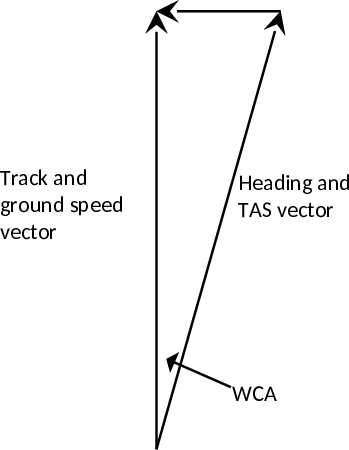
This MDR
technique works for the relatively small WCAs which are typical for medium to
high TAS values (the ground speed (GS) therefore can be assumed to be equal to
the TAS for application of the 1:60 rule).
Example 1:
Planned
track = 070° (T)
TAS =
400 kt
WV =
100° (T)/40 kt
WA = 30°
XWC = (0.5) ×
40
= 20 kt
20 kt
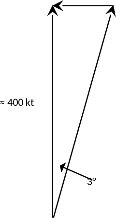
Heading
required = 073° (T)
GS is
determined by using the headwind/tailwind example previously explained.
WA = 30°
90° –
30° = 60°
HWC =
(0.9) × 40
= 36 kt
GS = 400
– 36 = 364 kt
Example 2:
Planned
track = 327° (T)
TAS =
240 kt
WV =
210° (T)/70 kt
WA = 60°
XWC =
(0.9) × 7
= 63 kt
63 kt
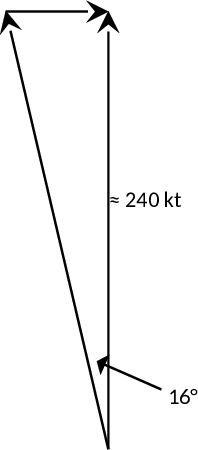
WCA = 16°
Heading
required = 311° (T)
GS is
determined by using the headwind/tailwind example previously explained.
WA = 60°
90° –
60° = 30°
TWC =
(0.5) × 70
= 35 kt
GS = 240
+ 35 = 275 kt
VFR
navigation (061 02 00 00)
The
techniques referred to within the LOs are based on the methods as described
below.
Mental
dead reckoning (MDR) off-track corrections
Based on
the 1:60 rule
1 NM of cross-track
error (XTE) for every 60 NM along track from waypoint = 1° of track error
angle (TKE).
1 NM of XTE
for every 60 NM along track to waypoint = 1° of closing angle (CA).
Change of
heading required to regain track in same distance as covered from waypoint to
position off track = 2 × TKE.
Change of
heading required to reach next waypoint from position off track = TKE + CA.
Example 1:
Planned
heading is 162° (T), and after 40 NM along track the aircraft position is
fixed 2 NM right of planned track. What heading is required to regain track in
approximately the same time as has taken to the fix position?
TKE = 3°
Heading
required = 156° (T)
Example 2:
Planned
heading is 317° (T), and after 22 NM along track the aircraft position is
fixed 3.5 NM left of planned track. What heading is required to fly direct to
the next waypoint which is another 45 NM down track?
TKE =
10°, CA = 5°
Heading
required = 332° (T)
Mental
dead reckoning (MDR) estimated time of arrival (ETA) calculations
Round the GS
to the nearest NM/min, and then make the same percentage adjustment for the
distance.
Example:
Distance
to go = 42 NM
GS = 132
kt
GS
rounded to 120 kt = 2 NM/min
Percentage
change = 10 %
Distance
= 42 – 10 % = 38 NM
Time =
38 / 2 = 19 min
Unsure-of-position
procedure
As soon as
the position of the aircraft is in doubt:
1. note the time;
2. communicate if in contact with an air
traffic control (ATC) unit to request assistance;
3. consider using any radio-navigation aids
that may be available to give position information (do not become distracted
from flying the aircraft safely);
4. if short of fuel or near controlled
airspace, and not in contact with ATC, set 121.5 MHz and make a PAN call;
5. if that is not necessary, check the
directional indicator (DI) and compass are still synchronised and continue to
fly straight and level and on route plan heading;
6. estimate the distance travelled since
the last known position;
7. compare the ground with your estimated
position on the map (look at the terrain for hills and valleys or line
features such as a motorway, railway, river or coastline);
8. once the position has been
re-established, keep checking the heading (and look out for other aircraft)
and continue the flight by updating the estimated position regularly while
looking for unique features such as a lake, wood, built-up area, mast, or a combination
of roads, rivers and railways.
Procedure
when lost
If the
unsure-of-position procedure does not resolve the problem:
1. inform someone — call first on the
working frequency and state the word ‘LOST’;
2. if there is no contact on that frequency
or there is no frequency selected, change to 121.5 MHz and make a PAN call;
select 7700 with ALT on the transponder if fitted.
In all
cases: maintain visual meteorological conditions (VMC), note the fuel state,
and try to identify an area suitable for a precautionary landing.
Consider the
‘HELP ME’ mnemonic:
H. High ground/obstructions — are there any
nearby?
E. Entering controlled airspace — is that a
possibility?
L. Limited experience, low time or student
pilot — let someone know.
P. PAN call in good time — don’t leave it
too late.
M. MET conditions — is the weather
deteriorating?
E. Endurance — is fuel getting low?
|
Syllabus reference |
BK |
Syllabus details and associated Learning
Objectives |
Aeroplane |
Helicopter |
IR |
CB-IR(A) |
BIR Exam |
BIR BK |
Remarks |
|||
|
ATPL |
CPL |
ATPL/IR |
ATPL |
CPL |
||||||||
|
060 00 00 00 |
|
NAVIGATION |
|
|
|
|
|
|
|
|
|
|
|
061 00 00 00 |
|
GENERAL NAVIGATION |
|
|
|
|
|
|
|
|
|
|
|
061 01 00 00 |
|
BASICS OF NAVIGATION |
|
|
|
|
|
|
|
|
|
|
|
061 01 01 00 |
|
The Earth |
|
|
|
|
|
|
|
|
|
|
|
061
01 01 01 |
|
Form |
|
|
|
|
|
|
|
|
|
|
|
(01) |
X |
State that the geoid is an irregular shape based on the surface of the oceans influenced only by gravity and centrifugal force. |
X |
X |
X |
X |
X |
|
|
|
|
|
|
(02) |
X |
State that a number of different ellipsoids are used to describe the shape of the Earth for mapping but that WGS-84 is the reference ellipsoid required for geographical coordinates. |
X |
X |
X |
X |
X |
|
|
|
|
|
|
(03) |
|
State that the circumference of the Earth is approximately 40 000 km or approximately 21 600 NM. |
X |
X |
X |
X |
X |
|
|
|
|
|
|
061
01 01 02 |
|
Earth
rotation |
|
|
|
|
|
|
|
|
|
|
|
(01) |
X |
Describe the rotation of the Earth around its own spin axis and the plane of the ecliptic (including the relationship of the spin axis to the plane of the ecliptic). |
X |
X |
X |
X |
X |
|
|
|
|
|
|
(02) |
|
Explain the effect that the inclination of the Earth’s spin axis has on insolation and duration of daylight. |
X |
X |
X |
X |
X |
|
|
|
|
|
|
061 01 02 00 |
|
Position |
|
|
|
|
|
|
|
|
|
|
|
061
01 02 01 |
|
Position
reference system |
|
|
|
|
|
|
|
|
|
|
|
(01) |
X |
State that geodetic latitude and longitude is used to define a position on the WGS-84 ellipsoid. |
X |
X |
X |
X |
X |
|
|
|
|
|
|
(02) |
|
Define geographic (geodetic) latitude and parallels of latitude. |
X |
X |
X |
X |
X |
|
|
|
|
|
|
(03) |
|
Calculate the difference in latitude between any two given positions. |
X |
X |
X |
X |
X |
|
|
|
|
|
|
(04) |
|
Define geographic (geodetic) longitude and meridians. |
X |
X |
X |
X |
X |
|
|
|
|
|
|
(05) |
|
Calculate the difference in longitude between any two given positions. |
X |
X |
X |
X |
X |
|
|
|
|
|
|
061 01 03 00 |
|
Direction |
|
|
|
|
|
|
|
|
|
|
|
061
01 03 01 |
|
Datums |
|
|
|
|
|
|
|
|
|
|
|
(01) |
X |
Define ‘true north’ (TN). |
X |
X |
X |
X |
X |
|
|
|
|
|
|
(02) |
|
Measure a true direction on any given aeronautical chart. |
X |
X |
X |
X |
X |
|
|
|
|
|
|
(03) |
X |
Define ‘magnetic north’ (MN). |
X |
X |
X |
X |
X |
|
|
|
|
|
|
(04) |
|
Define and apply variation. |
X |
X |
X |
X |
X |
|
|
|
|
|
|
(05) |
|
Explain changes of variation with time and position. |
X |
X |
X |
X |
X |
|
|
|
|
|
|
(06) |
X |
Define ‘compass north’ (CN). |
X |
X |
X |
X |
X |
|
|
|
|
|
|
(07) |
|
Apply deviation. |
X |
X |
X |
X |
X |
|
|
|
|
|
|
061
01 03 02 |
|
Track
and heading |
|
|
|
|
|
|
|
|
|
|
|
(01) |
|
Calculate XWC by: - trigonometry; and - MDR. |
X |
X |
X |
X |
X |
|
|
|
|
|
|
(02) |
|
Explain and apply the concepts of drift and WCA. |
X |
X |
X |
X |
X |
|
|
|
|
|
|
(03) |
|
Calculate the actual track with appropriate data of heading and drift. |
X |
X |
X |
X |
X |
|
|
|
|
|
|
(04) |
|
Calculate TKE with appropriate data of WCA and drift. |
X |
X |
X |
X |
X |
|
|
|
|
|
|
(05) |
|
Calculate the heading change at an off-course fix to directly reach the next waypoint using the 1:60 rule. |
X |
X |
X |
X |
X |
|
|
|
|
|
|
(06) |
|
Calculate the average drift angle based upon an off-course fix observation. |
X |
X |
X |
X |
X |
|
|
|
|
|
|
061 01 04 00 |
|
Distance |
|
|
|
|
|
|
|
|
|
|
|
061
01 04 01 |
|
WGS-84
ellipsoid |
|
|
|
|
|
|
|
|
|
|
|
(01) |
X |
State that 1 NM is equal to 1 852 km, which is the average distance of 1' of latitude change on the WGS-84 ellipsoid. |
X |
X |
X |
X |
X |
|
|
|
|
|
|
(02) |
|
State that 1' of longitude change at the equator on the WGS-84 ellipsoid is approximately equal to 1 NM. |
X |
X |
X |
X |
X |
|
|
|
|
|
|
061
01 04 02 |
|
Units |
|
|
|
|
|
|
|
|
|
|
|
(01) |
|
Convert between units of distance (nautical mile (NM), kilometre (km), statute mile (SM), feet (ft), inches (in)). |
X |
X |
X |
X |
X |
|
|
|
|
|
|
061
01 04 03 |
|
Graticule
distances |
|
|
|
|
|
|
|
|
|
|
|
(01) |
|
Calculate the distance between positions on the same meridian, on opposite (antipodal) meridians, on the same parallel of latitude, and calculate new latitude/longitude when given distances north‑south and east-west. |
X |
X |
X |
X |
X |
|
|
|
|
|
|
061
01 04 04 |
|
Air
mile |
|
|
|
|
|
|
|
|
|
|
|
(01) |
|
Evaluate the effect of wind and altitude on air distance. |
X |
X |
X |
X |
X |
|
|
|
|
|
|
(02) |
|
Convert between ground distance (NM) and air distance (NAM) using the formula: NAM = NM × TAS/GS. |
X |
X |
X |
X |
X |
|
|
|
|
|
|
061 01 05 00 |
|
Speed |
|
|
|
|
|
|
|
|
|
|
|
061
01 05 01 |
|
True
airspeed (TAS) |
|
|
|
|
|
|
|
|
|
|
|
(01) |
|
Calculate TAS from CAS, and CAS from TAS by: - mechanical computer; and - rule of thumb (2 % per 1 000 ft). |
X |
X |
X |
X |
X |
|
|
|
|
|
|
061
01 05 02 |
|
Mach
number (M) |
|
|
|
|
|
|
|
|
|
|
|
(01) |
|
Calculate TAS from M, and M from TAS. |
X |
X |
|
|
|
|
|
|
|
|
|
061
01 05 03 |
|
CAS/TAS/M
relationship |
|
|
|
|
|
|
|
|
|
|
|
(01) |
|
Deduce the CAS, TAS and M relationship in climb/descent/cruise (flying at constant CAS or M). |
X |
X |
|
|
|
|
|
|
|
|
|
(02) |
|
Deduce CAS and TAS in climb/descent/cruise (flying at constant CAS). |
|
|
X |
X |
X |
|
|
|
|
|
|
061
01 05 04 |
|
Ground
speed (GS) |
|
|
|
|
|
|
|
|
|
|
|
(01) |
|
Calculate headwind component (HWC) and tailwind component (TWC) by: - trigonometry; and - MDR. |
X |
X |
X |
X |
X |
|
|
|
|
|
|
(02) |
|
Apply HWC and TWC to determine GS from TAS and vice versa. |
X |
X |
X |
X |
|
|
|
|
|
|
|
(03) |
X |
Explain the relationship between GS and TAS with increasing WCA. |
X |
X |
X |
X |
X |
|
|
|
|
|
|
(04) |
|
Calculate GS with: - mechanical computer (TOV solution); and - MDR (given track, TAS and WV). |
X |
X |
X |
X |
X |
|
|
|
|
|
|
(05) |
|
Perform GS, distance and time calculations. |
X |
X |
X |
X |
X |
|
|
|
|
|
|
(06) |
|
Calculate revised GS to reach a waypoint at a specific time. |
X |
X |
X |
X |
X |
|
|
|
|
|
|
(07) |
|
Calculate the average GS based on two observed fixes. |
X |
X |
X |
X |
X |
|
|
|
|
|
|
061
01 05 05 |
|
Flight
log |
|
|
|
|
|
|
|
|
|
|
|
(01) |
|
Enter revised navigational en-route data, for the legs concerned, into the flight plan (e.g. updated wind and GS and correspondingly losses or gains in time and fuel consumption). |
X |
X |
X |
X |
X |
|
|
|
|
|
|
061
01 05 06 |
|
Gradient
versus rate of climb/descent |
|
|
|
|
|
|
|
|
|
|
|
(01) |
|
Estimate average climb/descent gradient (%) or glide path degrees according to the following rule of thumb: —
Gradient in degrees = (vertical distance (ft) / 100) / ground
distance (NM)) —
Gradient in % = (vertical distance (ft) / 60) / ground distance
(NM)) —
Gradient in degrees = arctan (altitude difference (ft) / ground
distance (ft)). N.B.
These rules of thumb approximate 1 NM to 6 000 ft and are
based on the 1:60 rule. |
X |
X |
X |
X |
X |
|
|
|
|
|
|
(02) |
|
Calculate rate of descent (ROD) on a given glide‑path angle or gradient using the following rule of thumb formulae: —
ROD (ft/min) = GP° × GS (NM/min) × 100 —
ROD (ft/min) = GP% × GS (kt) |
X |
X |
X |
X |
X |
|
|
|
|
|
|
(03) |
|
Calculate climb/descent gradient (ft/NM, % and degrees), GS or vertical speed according to the following formula: —
Vertical speed
(ft/min) = (GS (kt) × gradient (ft/NM)) / 60. |
X |
X |
X |
X |
X |
|
|
|
|
|
|
(04) |
X |
State that it is necessary to determine the position of the aircraft accurately before commencing descent in order to ensure safe ground clearance. |
X |
X |
X |
X |
X |
|
|
|
|
|
|
061 01 06 00 |
|
Triangle of velocities (TOV) |
|
|
|
|
|
|
|
|
|
|
|
061
01 06 01 |
|
Construction |
|
|
|
|
|
|
|
|
|
|
|
(01) |
|
Draw and correctly label the TOV. |
X |
X |
X |
X |
X |
|
|
|
|
|
|
061
01 06 02 |
|
Solutions |
|
|
|
|
|
|
|
|
|
|
|
(01) |
|
Resolve the TOV for: —
heading and GS (with mechanical
computer and MDR); —
WV (with mechanical computer);
and —
track and GS (with mechanical
computer and MDR. |
X |
X |
X |
X |
X |
|
|
|
|
|
|
061 01 07 00 |
|
Dead reckoning (DR) |
|
|
|
|
|
|
|
|
|
|
|
061
01 07 01 |
|
Dead
reckoning (DR) technique |
|
|
|
|
|
|
|
|
|
|
|
(01) |
|
Determine a DR position. |
X |
X |
X |
X |
X |
|
|
|
|
|
|
(02) |
|
Evaluate the difference between a DR and a fix position. |
X |
X |
X |
X |
X |
|
|
|
|
|
|
(03) |
|
Define ‘speed factor’ (SF). Speed divided by 60, used for mental flight-path calculations. |
X |
X |
X |
X |
X |
|
|
|
|
|
|
(04) |
|
Calculate wind correction angle (WCA) using the formula: —
WCA = XWC (crosswind
component)/SF |
X |
X |
X |
X |
X |
|
|
|
|
|
|
061 01 08 00 |
|
Navigation in climb and descent |
|
|
|
|
|
|
|
|
|
|
|
061
01 08 01 |
|
Average
airspeed |
|
|
|
|
|
|
|
|
|
|
|
(01) |
|
Average TAS used for climb problems is calculated at the altitude 2/3 of the cruising altitude. |
X |
X |
X |
X |
X |
|
|
|
|
|
|
(02) |
|
Average TAS used for descent problems is calculated at the altitude 1/2 of the descent altitude. |
X |
X |
X |
X |
X |
|
|
|
|
|
|
061
01 08 02 |
|
Average
wind velocity (WV) |
|
|
|
|
|
|
|
|
|
|
|
(01) |
|
WV used for climb problems is the WV at the altitude 2/3 of the cruising altitude. |
X |
X |
X |
X |
X |
|
|
|
|
|
|
(02) |
|
WV used for descent problems is the WV at the altitude 1/2 of the descent altitude. |
X |
X |
X |
X |
X |
|
|
|
|
|
|
(03) |
|
Calculate the average climb/descent GS from given TAS at various altitudes, and WV at various altitudes and true track. |
X |
X |
X |
X |
X |
|
|
|
|
|
|
061
01 08 03 |
|
Ground
speed (GS)/distance covered during climb or descent |
|
|
|
|
|
|
|
|
|
|
|
(01) |
X |
State that most aircraft operating handbooks supply graphical material to calculate climb and descent problems. |
X |
X |
X |
X |
X |
|
|
|
|
|
|
(02) |
|
Calculate the flying time and distance during climb/descent from given average rate of climb/descent and using average GS using the following formulae valid for a 3°-glide path: —
rate of descent = (GS × 10) / 2 —
rate of descent = speed factor
(SF) × glide‑path angle × 100 |
X |
X |
X |
X |
X |
|
|
|
|
|
|
(03) |
|
Given distance, speed and present altitude, calculate the rate of climb/descent in order to reach a certain position at a given altitude. |
X |
X |
X |
X |
X |
|
|
|
|
|
|
(04) |
|
Given speed, rate of climb/descent and altitude, calculate the distance required in order to reach a certain position at a given altitude. |
X |
X |
X |
X |
X |
|
|
|
|
|
|
(05) |
|
Given speed, distance to go and altitude to climb/descent, calculate the rate of climb/descent. |
X |
X |
X |
X |
X |
|
|
|
|
|
|
061 02 00 00 |
|
VISUAL FLIGHT RULES (VFR) NAVIGATION |
|
|
|
|
|
|
|
|
|
|
|
061 02 01 00 |
|
Ground features |
|
|
|
|
|
|
|
|
|
|
|
061
02 01 01 |
|
Ground
features |
|
|
|
|
|
|
|
|
|
|
|
(01) |
|
Recognise which elements would make a ground feature suitable for use for VFR navigation. |
X |
X |
X |
X |
X |
|
|
|
|
|
|
061
02 01 02 |
|
Visual
identification |
|
|
|
|
|
|
|
|
|
|
|
(01) |
|
Describe the problems of VFR navigation at lower levels and the causes of reduced visibility. |
X |
X |
X |
X |
X |
|
|
|
|
|
|
(02) |
|
Describe the problems of VFR navigation at night. |
X |
X |
X |
X |
X |
|
|
|
|
|
|
061 02 02 00 |
|
VFR navigation techniques |
|
|
|
|
|
|
|
|
|
|
|
061
02 02 01 |
|
Use
of visual observations and application to in-flight navigation |
|
|
|
|
|
|
|
|
|
|
|
(01) |
X |
Describe what is meant by the term ‘map reading’. |
X |
X |
X |
X |
X |
|
|
|
|
|
|
(02) |
X |
Define the term ‘visual checkpoint’. |
X |
X |
X |
X |
X |
|
|
|
|
|
|
(03) |
|
Discuss the general features of a visual checkpoint and give examples. |
X |
X |
X |
X |
X |
|
|
|
|
|
|
(04) |
|
State that the evaluation of the differences between DR positions and actual position can refine flight performance and navigation. |
X |
X |
X |
X |
X |
|
|
|
|
|
|
(05) |
X |
Establish fixes on navigational charts by plotting visually derived intersecting lines of position. |
X |
X |
X |
X |
X |
|
|
|
|
|
|
(06) |
X |
Describe the use of a single observed position line to check flight progress. |
X |
X |
X |
X |
X |
|
|
|
|
|
|
(07) |
X |
Describe how to prepare and align a map/chart for use in visual navigation. |
X |
X |
X |
X |
X |
|
|
|
|
|
|
(08) |
|
Describe visual-navigation techniques including: —
use of DR position to locate
identifiable landmarks; —
identification of charted
features/landmarks; —
factors affecting the selection
of landmarks; —
an understanding of seasonal
and meteorological effects on the appearance and visibility of landmarks; —
selection of suitable
landmarks; —
estimation of distance from
landmarks from successive bearings; —
estimation of the distance from
a landmark using an approximation of the sighting angle and the flight
altitude. |
X |
X |
X |
X |
X |
|
|
|
|
|
|
(09) |
|
Describe the action to be taken if there is no visual checkpoint available at a scheduled turning point. |
X |
X |
X |
X |
X |
|
|
|
|
|
|
(10) |
|
Understand the difficulties and limitations that may be encountered in map reading in some geographical areas due to the nature of terrain, lack of distinctive landmarks, or lack of detailed and accurate charted data. |
X |
X |
X |
X |
X |
|
|
|
|
|
|
(11) |
X |
State the function of contour lines on a topographical chart. |
X |
X |
X |
X |
X |
|
|
|
|
|
|
(12) |
X |
Indicate the role of ‘layer tinting’ (colour gradient) in relation to the depiction of topography on a chart. |
X |
X |
X |
X |
X |
|
|
|
|
|
|
(13) |
|
Using the contours shown on a chart, describe the appearance of a significant feature. |
X |
X |
X |
X |
X |
|
|
|
|
|
|
(14) |
|
Apply the techniques of DR, map reading, orientation, timing and revision of ETAs and headings. |
X |
X |
X |
X |
X |
|
|
|
|
|
|
061
02 02 02 |
|
Unplanned
events |
|
|
|
|
|
|
|
|
|
|
|
(01) |
|
Explain what needs to be considered in case of diversion, when unsure of position and when lost. |
X |
X |
X |
X |
X |
|
|
|
|
|
|
061 03 00 00 |
|
GREAT CIRCLES AND RHUMB LINES |
|
|
|
|
|
|
|
|
|
|
|
061 03 01 00 |
|
Great circles |
|
|
|
|
|
|
|
|
|
|
|
061
03 01 01 |
|
Properties |
|
|
|
|
|
|
|
|
|
|
|
(01) |
|
Describe the geometric properties of a great circle (including the vertex) and a small circle. |
X |
X |
|
|
|
|
|
|
|
|
|
(02) |
|
Describe the geometric properties of a great circle and a small circle, up to 30° difference of longitude. |
|
|
X |
X |
X |
|
|
|
|
|
|
(03) |
X |
Explain why a great-circle route is the shortest distance between any two positions on the Earth. |
X |
X |
X |
X |
X |
|
|
|
|
|
|
(04) |
|
Name examples of great circles on the surface of the Earth. |
X |
X |
X |
X |
X |
|
|
|
|
|
|
061
03 01 02 |
|
Convergence |
|
|
|
|
|
|
|
|
|
|
|
(01) |
X |
Explain why the track direction of a great-circle route (other than following a meridian or the equator) changes. |
X |
X |
X |
X |
X |
|
|
|
|
|
|
(02) |
|
State the formula used to approximate the value of Earth convergence as change of longitude × sine mean latitude. |
X |
X |
X |
X |
X |
|
|
|
|
|
|
(03) |
|
Calculate the approximate value of Earth convergence between any two positions, up to 30° difference of longitude. |
X |
X |
X |
X |
X |
|
|
|
|
|
|
061 03 02 00 |
|
Rhumb lines |
|
|
|
|
|
|
|
|
|
|
|
061
03 02 01 |
|
Properties |
|
|
|
|
|
|
|
|
|
|
|
(01) |
X |
Describe the geometric properties of a rhumb line. |
X |
X |
X |
X |
X |
|
|
|
|
|
|
(02) |
X |
State that a rhumb-line route is not the shortest distance between any two positions on the Earth (excluding meridians and equator). |
X |
X |
X |
X |
X |
|
|
|
|
|
|
061 03 03 00 |
|
Relationship |
|
|
|
|
|
|
|
|
|
|
|
061
03 03 01 |
|
Distances |
|
|
|
|
|
|
|
|
|
|
|
(01) |
|
Explain that the variation in distance of the great‑circle route and rhumb-line route between any two positions increases with increasing latitude or change in longitude. |
X |
X |
X |
X |
X |
|
|
|
|
|
|
061
03 03 02 |
|
Conversion
angle |
|
|
|
|
|
|
|
|
|
|
|
(01) |
|
Calculate and apply the conversion angle. |
X |
X |
|
|
|
|
|
|
|
|
|
061 04 00 00 |
|
CHARTS |
|
|
|
|
|
|
|
|
|
|
|
061 04 01 00 |
|
Chart requirements |
|
|
|
|
|
|
|
|
|
|
|
061
04 01 01 |
|
ICAO
Annex 4 ‘Aeronautical Charts’ |
|
|
|
|
|
|
|
|
|
|
|
(01) |
|
State the requirement for conformality and for a straight line to approximate a great circle. |
X |
X |
X |
X |
X |
|
|
|
|
|
|
061
04 01 02 |
|
Convergence |
|
|
|
|
|
|
|
|
|
|
|
(01) |
|
Explain and calculate the constant of the cone (sine of parallel of origin). |
X |
X |
X |
X |
X |
|
|
|
|
|
|
(02) |
|
Explain the relationship between Earth and chart convergence with respect to the ICAO requirement for a straight line to approximate a great circle. |
X |
X |
X |
X |
X |
|
|
|
|
|
|
061 04 01 03 |
|
Scale |
|
|
|
|
|
|
|
|
|
|
|
(01) |
|
Recognise methods of representing scale on aeronautical charts. |
X |
X |
X |
X |
X |
|
|
|
|
|
|
(02) |
|
Perform scale calculations based on typical en‑route chart scales. |
X |
X |
X |
X |
X |
|
|
|
|
|
|
061 04 02 00 |
|
Projections |
|
|
|
|
|
|
|
|
|
|
|
061
04 02 01 |
|
Methods
of projection |
|
|
|
|
|
|
|
|
|
|
|
(01) |
X |
Identify azimuthal, cylindrical and conical projections. |
X |
X |
X |
X |
X |
|
|
|
|
|
|
061
04 02 02 |
|
Polar
stereographic |
|
|
|
|
|
|
|
|
|
|
|
(01) |
|
State the properties of a polar stereographic projection. |
X |
X |
X |
X |
X |
|
|
|
|
|
|
(02) |
|
Calculate straight line track changes on a polar stereographic chart. |
X |
X |
X |
X |
X |
|
|
|
|
|
|
061
04 02 03 |
|
Direct
Mercator |
|
|
|
|
|
|
|
|
|
|
|
(01) |
|
State the properties of a direct Mercator projection. |
X |
X |
X |
X |
X |
|
|
|
|
|
|
(02) |
|
Given the scale at one latitude, calculate the scale at different latitudes. |
X |
X |
X |
X |
X |
|
|
|
|
|
|
(03) |
|
Given a chart length at one latitude, show that it represents a different Earth distance at other latitudes. |
X |
X |
X |
X |
X |
|
|
|
|
|
|
061
04 02 04 |
|
Lambert |
|
|
|
|
|
|
|
|
|
|
|
(01) |
|
State the properties of a Lambert projection. |
X |
X |
X |
X |
X |
|
|
|
|
|
|
(02) |
|
Calculate straight line track changes on a Lambert chart. |
X |
X |
X |
X |
X |
|
|
|
|
|
|
(03) |
|
Explain the scale variation throughout the charts as follows: —
the scale indicated on the chart will be correct at the standard
parallels; —
the scale will increase away from the parallel of origin; —
the
scale within the standard parallels differs by less than 1 % from the
scale stated on the chart. |
X |
X |
X |
X |
X |
|
|
|
|
|
|
(04) |
|
Given appropriate data, calculate initial, final or rhumb-line tracks between two positions (lat./long.). |
X |
X |
X |
X |
X |
|
|
|
|
|
|
(05) |
|
Given two positions (lat./long.) and information to determine convergency between the two positions, calculate the parallel of origin. |
X |
X |
X |
X |
X |
|
|
|
|
|
|
(06) |
|
Given a Lambert chart, determine the parallel of origin, or constant of cone. |
X |
X |
X |
X |
X |
|
|
|
|
|
|
(07) |
|
Given constant of cone or parallel of origin, great‑circle track at one position and great-circle track at another position, calculate the difference of longitude between the two positions. |
X |
X |
X |
X |
X |
|
|
|
|
|
|
061 04 03 00 |
|
Practical use |
|
|
|
|
|
|
|
|
|
|
|
061
04 03 01 |
|
Symbology |
|
|
|
|
|
|
|
|
|
|
|
(01) |
|
Recognise ICAO Annex 4 symbology. |
X |
X |
X |
X |
X |
|
|
|
|
|
|
061
04 03 02 |
|
Plotting |
|
|
|
|
|
|
|
|
|
|
|
(01) |
|
Measure tracks and distances on VFR and IFR en‑route charts. |
X |
X |
X |
X |
X |
|
|
|
|
|
|
(02) |
|
Fix the aircraft position on an en-route chart with information from VOR and DME equipment. |
X |
X |
X |
X |
X |
|
|
|
|
|
|
(03) |
|
Resolve bearings of an NDB station for plotting on an aeronautical chart. |
X |
X |
X |
X |
X |
|
|
|
|
|
|
061 05 00 00 |
|
TIME |
|
|
|
|
|
|
|
|
|
|
|
061 05 01 00 |
|
Local Mean Time (LMT) |
|
|
|
|
|
|
|
|
|
|
|
061
05 01 01 |
|
Mean
solar day |
|
|
|
|
|
|
|
|
|
|
|
(01) |
X |
Explain the concepts of a mean solar day and LMT. |
X |
X |
X |
X |
X |
|
|
|
|
|
|
061
05 01 02 |
|
Local
Mean Time (LMT) and Universal Time Coordinated (UTC) |
|
|
|
|
|
|
|
|
|
|
|
(01) |
|
Perform LMT and UTC calculations. |
X |
X |
X |
X |
X |
|
|
|
|
|
|
061 05 02 00 |
|
Standard time |
|
|
|
|
|
|
|
|
|
|
|
061
05 02 01 |
|
Standard
time and daylight saving time |
|
|
|
|
|
|
|
|
|
|
|
(01) |
|
Explain and apply the concept of standard time and daylight saving time, and perform standard time and daylight saving time calculations. |
X |
X |
X |
X |
X |
|
|
|
|
|
|
061
05 02 02 |
|
International
Date Line |
|
|
|
|
|
|
|
|
|
|
|
(01) |
|
State the changes when crossing the International Date Line. |
X |
X |
X |
X |
X |
|
|
|
|
|
|
061 05 03 00 |
|
Sunrise and sunset |
|
|
|
|
|
|
|
|
|
|
|
061
05 03 01 |
|
Sunrise
and sunset times |
|
|
|
|
|
|
|
|
|
|
|
(01) |
|
Define sunrise, sunset, and civil twilight, and extract times from a suitable source (e.g. an almanac). |
X |
X |
X |
X |
X |
|
|
|
|
|
|
(02) |
|
Explain the changes to sunrise, sunset, and civil twilight times with date, latitude and altitude. |
X |
X |
X |
X |
X |
|
|
|
|
|
|
(03) |
|
Explain at which time of the year the duration of daylight changes at the highest rate. |
X |
X |
X |
X |
X |
|
|
|
|
|