GM2 ADR.OPS.A.005(a) Aerodrome data
ED Decision 2014/012/R
SURVEYING REQUIREMENTS FOR RUNWAY THRESHOLDS, TAXIWAYS AND AIRCRAFT STANDS
(a) Thresholds
(1) For surveying purposes, threshold positions must be taken as being at the geometric centre of the runway and at the beginning of the paved surface, i.e. the beginning of that portion of the runway usable for landing. Where thresholds are marked by appropriate threshold markings (e.g. displaced thresholds), these must be taken as the threshold points. Where threshold lighting is surveyed, the locations must be described on the diagram accompanying the report. Where there is no threshold lighting, an appropriate point for survey in accordance with the following figures must be selected.
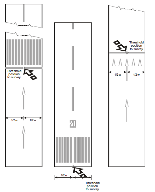
Figure 1
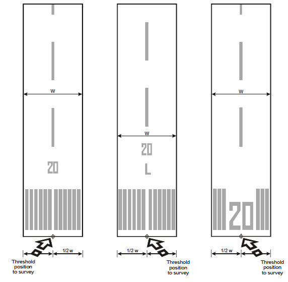
Figure 2
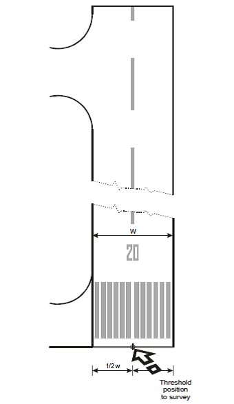
Figure 3
(2) If the runway has only one threshold certified for landing, the runway end position must be surveyed. For surveying purposes, the runway end position (flight path alignment point) must be taken as being at the geometric centre of the runway and at the end of the paved surface, i.e. the end of that portion of the runway usable for landing.
(b) Taxiways and stand/checkpoints — General
(1) Except as provided in (c) (1) below, for surveying purposes the centre (mid-width) of the taxiway centre line marking, apron taxilane marking or the aircraft stand guide line marking must be taken as the reference data.
(2) The points of commencement and ends of straight sections of taxiways, apron taxilanes and aircraft stand point guidance lines markings must be surveyed. Sufficient additional points must be surveyed to maintain the required accuracy along the lines.
(3) For curved sections of taxiways, apron taxilanes and aircraft stand guide line markings, the commencement and end of the curved section centre line must be surveyed together with the position of the centre point of the arc and its radius. In the case of a compound curve, the centre and radius of each arc and the commencement and end of each of the arcs must be surveyed. Where this is impracticable in the field, a series of sequential points must be surveyed along the curved section of the centre line with a maximum arc to chord distance not exceeding 0.25 m for taxiways and 0.10 m for apron taxilanes and aircraft stand guide line markings. Sufficient points must be surveyed to maintain the required accuracy along the lines. The surveyor must, in processing the data, conduct a graphical inspection of the survey points to ensure collinearity.
(c) Taxiways
(1) To permit uninterrupted transition from the actual runway centre line to the taxiway centre line and to provide the required continuity of guidance for the aircraft navigation data base, differentiation must be made between the surface markings and the actual path the aircraft must follow. Therefore, for the guidance of aircraft entering or exiting the runway for take-off or landing, the following must be surveyed:
(i) the point at which the radius of turn, prescribed by the appropriate authority for each taxiway, is tangential to the runway centre line, and the point at which that radius of turn joins the taxiway centre line marking at a tangent;
(ii) the point that prescribes the centre of the arc; and
(iii) the radius of the arc.
Where this is impracticable in the field, a series of sequential points must be surveyed along the curved section of the centre line of taxiways.
(2) Where taxiway centre line marking is provided on a runway that is part of a standard taxi route, or a taxiway centre line is not coincident with runway centre line, the following points must be surveyed:
(i) the point on the taxiway marking at which the taxiway enters the runway;
(ii) the points at which the taxiway deviates from a straight line;
(iii) the intersection of the taxiway centre line marking and boundary of each ‘block’ that has been published as part of the aerodrome movement and guidance control system; and
(iv) the point on the taxiway marking at which the taxiway exits the runway.
(3) In defining taxiways, the following points must be surveyed at the centre of the centre line marking of each taxiway, as appropriate:
(i) intermediate holding positions and runway holding positions (including those associated with the intersection of a runway with another runway when the former runway is part of a standard taxi route) and for points established for the protection of sensitive areas for radio navigation aids;
(ii) taxiway intersection markings;
(iii) intersection of other taxiways, including taxiways described in point (c) (2) above;
(iv) intersections of ‘blocks’ defined for surface movement, guidance and control systems;
(v) commencement and end of selectable taxiway lighting systems provided as part of the surface movement, guidance and control systems, where different from subparagraph (iv) above; and
(d) Aircraft stand points
(1) In defining the aircraft stands, the following points must be surveyed at the centre of the guide line marking of the aircraft stands, as appropriate:
(i) taxilane centre lines;
(ii) lead-in line(s);
(iii) turning line;
(iv) straight section of the turning line;
(v) nose wheel stopping position;
(vi) true heading of the alignment bar; and
(vii) lead-out line(s).
(2) Where aircraft stands are utilized by more than one aircraft type and different guide line markings exist, a diagram must be prepared by the surveyor showing the arrangement of the markings in use, together with an indication of the points surveyed. Where all the stands at an aerodrome/heliport are marked uniformly, only a single diagram needs to be prepared.
The points that should be surveyed for a taxiway or an aircraft stand, are shown in the following diagrams:
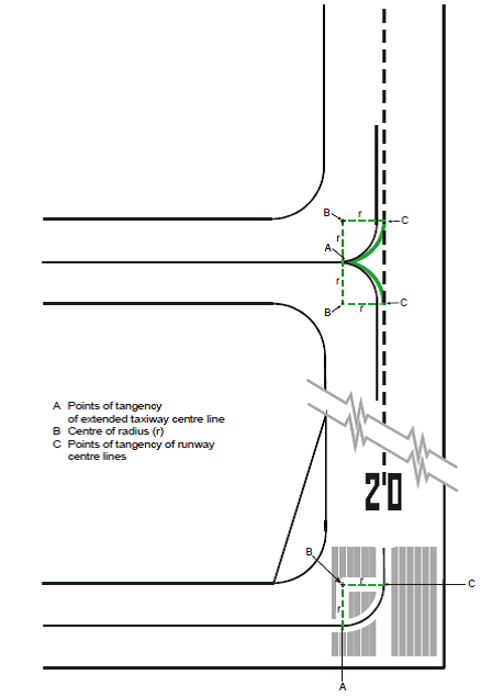
Figure 4 - Runway and taxiway intersections to be surveyed
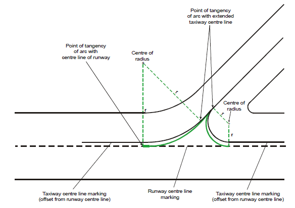
Figure 5 - Runway and taxiway intersections to be surveyed
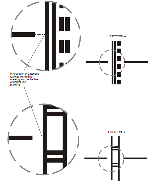
Figure 6 - Runway holding positions to be surveyed
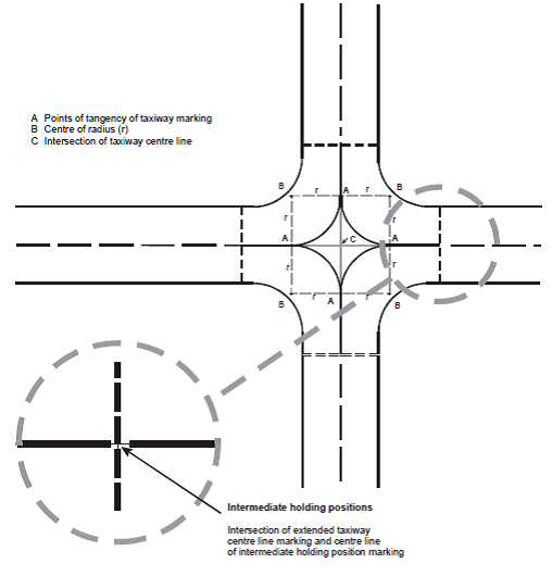
Figure 7 - Taxiway intersections to be surveyed
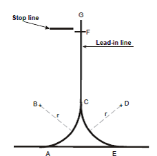
Figure 8 - Simple nose wheel lead-in line
-
Position
Description of point to be surveyed
A
Point of tangency of centre of lead-in marking with centre of taxilane marking
B
Centre of arc of lead-in line and radius
C
Point of tangency with centre of lead-in line marking
D
Centre of arc of lead-in line and radius
E
Point of tangency of centre of lead-in marking with centre of taxilane marking
F
Nose wheel position of parked aircraft
G
End of lead-in line marking
Table 1
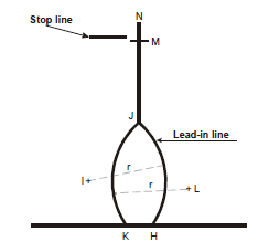
Figure 9 - Offset nose wheel lead-in line
-
Position
Description of point to be surveyed
H
Intersection of centre of lead-in line marking and centre of taxilane marking
I
Centre of arc of lead-in line and radius
J
Centre of commencement of straight section of lead-in line
K
Intersection of centre of lead-in line marking and centre of taxilane marking
L
Centre of arc of lead-in line and radius
M
Nosewheel position of parked aircraft
N
End of lead-in line marking
Table 2
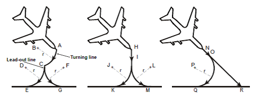
Figure 10 - Simple nose wheel lead-out lines
-
Position
Description of point to be surveyed
A
Centre of commencement of turning line marking
B
Centre of arc of turning line and radius
C
Centre of intersection of turning line marking and lead-out line marking
D
Centre of arc of lead-out line and radius
E
Point of tangency of centre of lead-out line marking and taxilane marking
F
Centre of arc of lead-out line and radius
G
Point of tangency of centre of lead-out line marking and taxilane marking
H
Commencement of lead-out line
I
Centre of commencement of curved section of lead-out line
J
Centre of arc of lead-out line and radius
K
Point of tangency of centre of lead-out line marking and taxilane marking
L
Centre of arc of lead-out line and radius
M
Point of tangency of centre of lead-out line marking and taxilane marking
N
Point of tangency of centre of lead-out line marking and taxilane marking
O
Centre of commencement of curved section of lead-out line
P
Centre of arc of lead-out line and radius
Q
Point of tangency of centre of lead-out line marking and taxilane marking
R
Intersection of centre of lead-out line marking and taxilane marking
Table 3
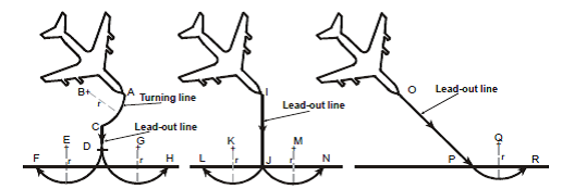
Figure 11 - Offset nose wheel lead-out lines
-
Position
Description of point to be surveyed
A
Centre of commencement of turning line marking
B
Centre of arc of turning line and radius
C
Centre of intersection of turning line marking and lead-out line marking
D
Centre of end of straight section of lead-out line marking
E
Centre of arc of lead-out line and radius
F
Intersection of centre of lead-out line marking and taxilane marking
G
Centre of arc of lead-out line and radius
H
Intersection of centre of lead-out line marking and taxilane marking
I
Commencement of lead-out line
J
Centre of commencement of curved section of lead-out line
K
Centre of arc of lead-out line and radius
L
Intersection of centre of lead-out line marking and taxilane marking
M
Centre of arc of lead-out line and radius
N
Intersection of centre of lead-out line marking and taxilane marking
O
Commencement of lead-out line
P
Centre of commencement of curved section of lead-out line
Q
Centre of arc of lead-out line and radius
R
Intersection of centre of lead-out line marking and taxilane marking
Table 4
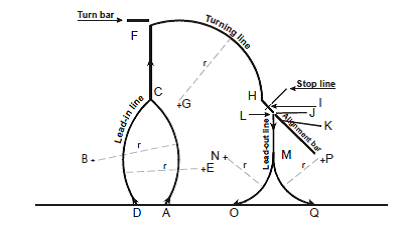
Figure 12 - Turning lines
-
Position
Description of point to be surveyed
A
Intersection of centre of lead-in line marking and centre of taxilane marking
B
Centre of arc of lead-in line and radius
C
Centre of commencement of straight section of lead-in line
D
Intersection of centre of lead-in line marking and centre of taxilane marking
E
Centre of arc of lead-in line and radius
F
End of straight section of lead-in line marking/commencement of turning line marking
G
Centre of arc of turning line and radius
H
Centre of commencement of straight section of turning line marking
I
Nose wheel position of parked aircraft
J
Centre of end of straight section or turning line marking
K
True bearing of alignment bar
L
Commencement of lead-out line
M
Centre of commencement of curved section of lead-out line
N
Centre of arc of lead-out line and radius
O
Point of tangency of centre of lead-out line marking and taxilane marking
P
Centre of arc of lead-out line and radius
Q
Point of tangency of centre of lead-out line marking and taxilane marking
Table 5