CS ADR-DSN.M.650 Approach slope and elevation setting of light units for PAPI and APAPI
ED Decision 2022/006/R
(a) Approach slope:
(1) The approach slope as defined in Figure M-5, should be so designed to be appropriate for use by the aeroplanes in the approach.
(2) When the runway is equipped with an ILS and/or MLS, the siting and the angle of elevation of the light units should be such that the visual approach slope conforms as closely as possible with the glide path of the ILS and/or the minimum glide path of the MLS, as appropriate.
(b) Elevation setting of light units
(1) The angle of elevation settings of the light units in a PAPI wing bar should be such that, during an approach, the pilot of an aeroplane observing a signal of one white and three reds should clear all objects in the approach area by a safe margin (see Table M-1).
(2) The angle of elevation settings of the light units in an APAPI wing bar should be such that, during an approach, the pilot of an aeroplane observing the lowest on-slope signal, i.e. one white and one red, should clear all objects in the approach area by a safe margin (see Table M-1).
(3) The azimuth spread of the light beam should be suitably restricted where an object located outside the obstacle protection surface of the PAPI or APAPI system but within the lateral limits of its light beam, is found to extend above the plane of the obstacle protection surface and a safety assessment indicates that the object could adversely affect the safety of operations. The extent of the restriction should be such that the object remains outside the confines of the light beam.
(4) Where wing bars are installed on each side of the runway to provide roll guidance, corresponding units should be set at the same angle so that the signals of each wing bar change symmetrically at the same time.
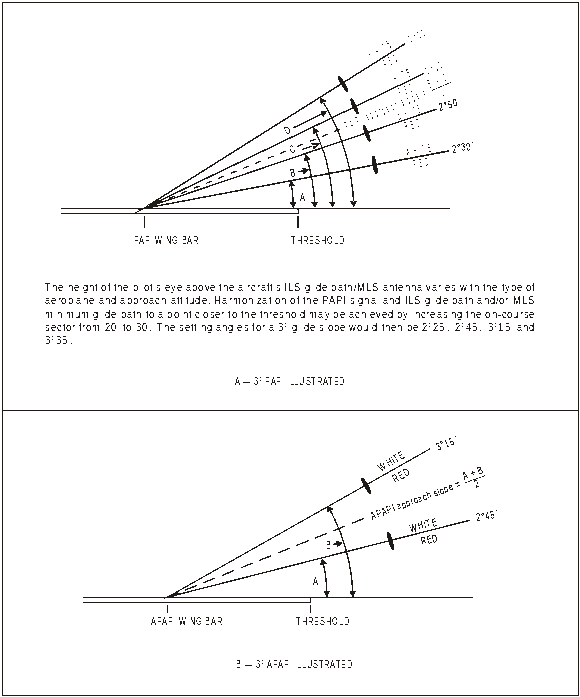
Figure M-5. Light beams and angle of elevation setting of PAPI and APAPI
Eye-to-wheel height of aeroplane in the approach configurationa |
Desired wheel clearance (metres)b, c |
Minimum wheel clearance (metres)d |
(1) |
(2) |
(3) |
up to but not including 3 m |
6 |
3e |
3 m up to but not including 5 m |
9 |
4 |
5 m up to but not including 8 m |
9 |
5 |
8 m up to but not including 14 m |
9 |
6 |
a. In
selecting the eye-to-wheel height group, only aeroplanes meant to
use the system on a regular basis should be considered. The most
demanding amongst such aeroplanes should determine the
b. Where practicable, the desired wheel clearances shown in column (2) should be provided. c. The wheel clearances in column (2) should be reduced to no less than those in column (3) where a safety assessment indicates that such reduced wheel clearances are acceptable. d. When a reduced wheel clearance is provided at a displaced threshold, it should be ensured that the corresponding desired wheel clearance specified in column (2) should be available when an aeroplane at the top end of the eye-to-wheel height group chosen overflies the extremity of the runway. e. This wheel clearance should be reduced to 1.5 m on runways used mainly by light-weight non-turbo-jet aeroplanes. |
||
Table M-1. Wheel clearance over threshold for PAPI and APAPI
[Issue: ADR-DSN/3]
[Issue: ADR-DSN/6]