GM2 CAT.POL.A.310 Take-off obstacle
clearance – multi-engined aeroplanes
TAKE-OFF FLIGHT PATH CONSTRUCTION
(a) This GM provides examples to illustrate the method of take-off flight path construction given in AMC2 CAT.POL.A.310. The examples are based on an aeroplane for which the AFM shows, at a given mass, altitude, temperature and wind component the following performance data:
— factored take-off distance – 1 000 m;
— take-off speed, V2 – 90 kt;
— en-route climb speed, VERC – 120 kt;
— en-route all-engines climb gradient, YERC – 0.2;
— en-route OEI climb gradient, YERC-1 – 0.032.
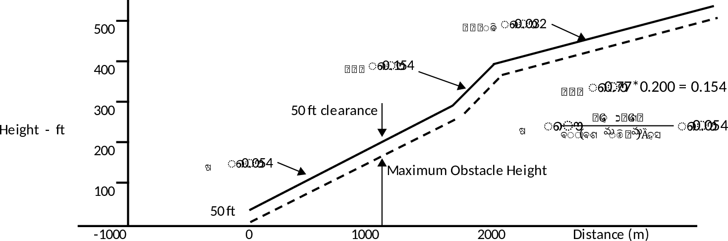
(1) Assumed engine failure height 300 ft
The average all-engines gradient from 50 ft to 300 ft may be read from Figure 1 or calculated with the following formula:

The factor of 0.77 as required by CAT.POL.A.310 is already included where:
— Y300 = average all-engines gradient from 50 ft to 300 ft;
— YERC = scheduled all engines en-route gross climb gradient;
— VERC = en-route climb speed, all engines knots TAS; and
— V2 = take-off speed at 50 ft, knots TAS.
Figure
1
Assumed engine failure height 300 ft
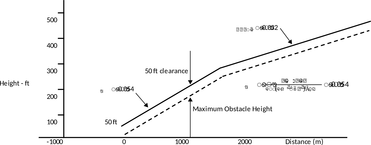
(2) Assumed engine failure height 200 ft
The average all-engines gradient from 50 ft to 200 ft may be read from Figure 2 or calculated with the following formula:

The factor of 0.77 as required by CAT.POL.A.310 is already included where:
— Y200 = average all-engines gradient from 50 ft to 200 ft;
— YERC = scheduled all engines en-route gross gradient;
— VERC = en-route climb speed, all engines, knots TAS; and
— V2 = take-off speed at 50 ft, knots TAS.
Figure
2
Assumed engine failure height 200 ft
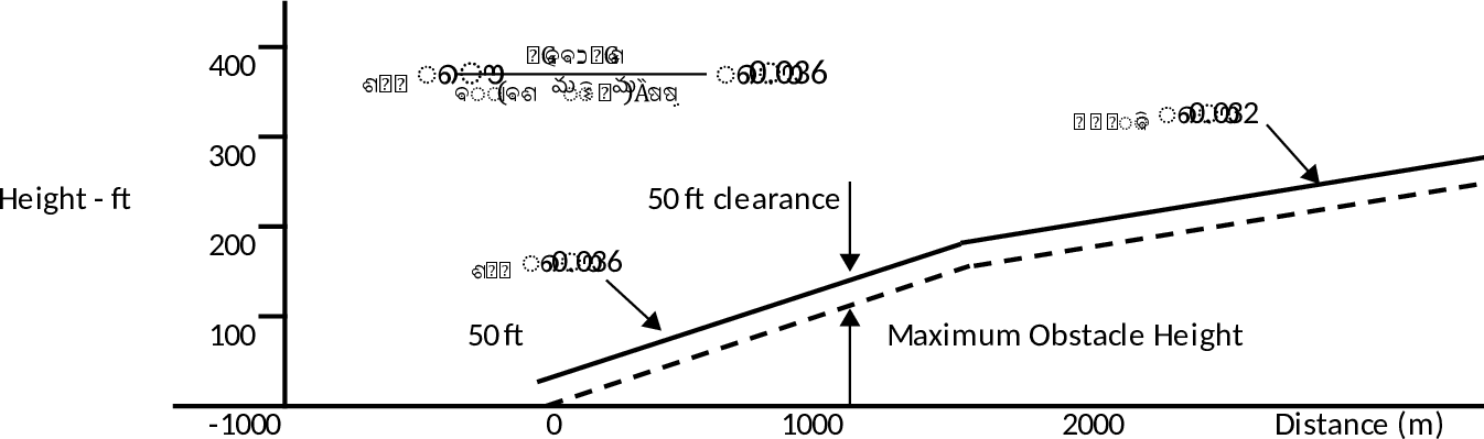
(3) Assumed engine failure height less than 200 ft
Construction of a take-off flight path is only possible if the AFM contains the required flight path data.
(4) Assumed engine failure height more than 300 ft
The construction of a take-off flight path for an assumed engine failure height of 400 ft is illustrated below.
Figure
3
Assumed engine failure height less than 200 ft