AMC 20-158A Aircraft
electrical and electronic system high-intensity radiated fields (HIRF)
protection
ED Decision 2022/001/R
1. PURPOSE
a. This AMC describes an acceptable means, but not the only means, for demonstrating compliance with the applicable certification specifications (CSs) related to high-intensity radiated fields (HIRF) protection (CS 23.1308, 25.1317, 27.1317, and 29.1317). Compliance with this AMC is not mandatory, and an applicant may elect to use an alternative means of compliance. However, the alternative means of compliance must meet the relevant requirements, ensure an equivalent level of safety, and be approved by EASA on a product or ETSO article basis.
b. The modal verb ‘must’ is used to indicate which means are necessary to demonstrate compliance with the applicable CSs by using this AMC. The modal verb ‘should’ is used when following the AMC to indicate that an action is recommended but is not necessary to demonstrate compliance with the applicable CSs when using this AMC.
2. SCOPE AND APPLICABILITY
This AMC provides possible means to demonstrate compliance with CS 23.1308/23.2520, 25.1317, 27.1317, and 29.1317 for the effects of HIRFs. This AMC may be used by applicants for a new type certificate (TC) or a change to an existing TC when the certification basis requires to address the above-mentioned CSs.
Note: For CS-23 Amendment 5 and higher, a new HIRF specification, i.e. CS 23.2520, which differs from the previous CS 23.1308, is included. The associated AMC to CS 23.2520 are published separately in the AMC & GM to CS-23, based on ASTM F3061/F3061M-17 and F3236-17.This AMC could nevertheless be used as guidance for demonstrating compliance with CS 23.2520.
3. DOCUMENT HISTORY
This AMC supersedesAMC 20-158, Aircraft Electrical and Electronic System High-Intensity Radiated Fields (HIRF) Protection, dated 15 July 2015.
4. RELATED MATERIAL
a. European
Union Aviation Safety Agency (EASA) (in this document also referred to as ‘the
Agency’)
Certification Specifications:
1. CS 23.1308, CS 25.1317, CS 27.1317, and CS 29.1317, High-intensity Radiated Fields (HIRF) Protection;
2. CS 23.1309, CS 25.1309, CS 27.1309, and CS 29.1309, Equipment, systems, and installations; and
3. CS 23.1529, CS 25.1529, CS 27.1529, and CS 29.1529, Instructions for Continued Airworthiness.
EASA Certification Specifications (CSs) and Acceptable Means of Compliance (AMC) may be downloaded from the EASA website at www.easa.europa.eu.
b. FAA
Advisory Circulars (ACs)
1. AC 23.1309-1E, System Safety Analysis and Assessment for Part 23 Airplanes;
2. AC 25.1309-1A, System Design and Analysis;
3. AC-27-1B, Certification of Normal Category Rotorcraft;
4. AC-29-2C, Certification of Transport Category Rotorcraft, or later revisions;
5. AC 20-158A, The Certification of Aircraft Electrical and Electronic Systems for Operation in the High‑Intensity Radiated Fields (HIRF) Environment.
Applicants can view and download copies from the web-based FAA Regulatory and Guidance Library (RGL) at www.airweb.faa.gov. On the RGL website, the applicant should select ‘Advisory Circular’, then select ‘By Number’. ACs are also available on the FAA website at http://www.faa.gov/regulations_policies/advisory_circulars/.
c. European
Organisation for Civil Aviation Equipment (EUROCAE)
Copies of these documents can be requested from EUROCAE, 102 rue Etienne Dolet, 92240 Malakoff, France; Telephone: +33 1 40 92 79 30; Fax: +33 1 46 55 62 65; Website: http://www.eurocae.net.
1. EUROCAE ED-107A, Guide to certification of Aircraft in a High Intensity Radiated Field (HIRF) Environment;
2. EUROCAE ED-14G, Environmental Conditions and Test Procedures for Airborne Equipment;
3. EUROCAE ED-79A, Guidelines for Development of Civil Aircraft and Systems;
4. EUROCAE ED-234, User Guide Supplement to EUROCAE ED-14G.
EUROCAE documents may be purchased from:
European Organisation for Civil Aviation Equipment
9-23 rue Paul Lafargue
"Le Triangle" building
93200 Saint-Denis, France
Telephone: +33 1 49 46 19 65
(Email: [email protected], website: www.eurocae.net
d. Radio
Technical Commission for Aeronautics (RTCA)
RTCA/DO-160G, Environmental Conditions and Test Procedures for Airborne Equipment. This document is technically equivalent to EUROCAE ED-14G.
RTCA documents may be purchased from:
RTCA, Inc., 1150 18th Street NW, Suite 910, Washington D.C. 20036, USA
(Email: [email protected], website: www.rtca.org
e. Society
of Automotive Engineers (SAE International)
1. SAE Aerospace Recommended Practice (ARP)5583A,Guide to Certification of Aircraft in a High Intensity Radiated Field (HIRF) Environment. SAE ARP 5583A and ED-107A are technically equivalent and either document may serve as the ‘User’s Guide’ referred to in this AMC.
2. SAE ARP 4754A, Guidelines For Development Of Civil Aircraft And Systems, dated December 2010. This document is technically equivalent to EUROCAE ED-79A.
3. SAE ARP 4761, Guidelines and Methods for Conducting the Safety Assessment Process on Civil Airborne Systems and Equipment, dated December 1996.
SAE International documents may be purchased from:
SAE Customer Service
400 Commonwealth Drive
Warrendale, PA
15096-0001, USA
Website: http://www.sae.org
5. BACKGROUND
a. Aircraft protection. The need for the protection of aircraft electrical and electronic systems has increased substantially in recent years for the following reasons:
1. greater dependence on electrical and electronic systems performing functions required for continued safe flight and landing of an aircraft;
2. the reduced electromagnetic shielding afforded by some composite materials used in aircraft designs;
3. the increased susceptibility of electrical and electronic systems to HIRF because of increased data bus and processor operating speeds, higher-density integrated circuits and cards, and greater sensitivities of electronic equipment;
4. expanded frequency usage, especially above 1 gigahertz (GHz)
5. the increased severity of the HIRF environment because of an increase in the number and radiated power of radio frequency (RF) transmitters; and
6. the adverse effects experienced by some aircraft when exposed to HIRF.
b. HIRF environment. The electromagnetic HIRF environment exists because of the transmission of electromagnetic RF energy from radar, radio, television, and other ground-based, shipborne, or airborne RF transmitters. The User’s Guide (SAE ARP 5583A/EUROCAE ED-107A) provides a detailed description of the derivation of these HIRF environments.
6. APPROACHES
TO COMPLIANCE
a. General. The following activities should be elements of a proper HIRF certification programme. Adherence to the sequence shown is not necessary. More detailed information on HIRF certification compliance is provided in the User’s Guide (ED-107A).
The applicantshould:
1. identify the systems to be assessed;
2. establish the applicable aircraft external HIRF environment;
3. establish the test environment for installed systems;
4. apply the appropriate method of HIRF compliance verification;
5. verify the effectiveness of the HIRF protection; and
6. take corrective measures (if needed).
More detailed information on these activities is proposed in Sections7 and 8 of this AMC.
b. Identify the systems to be assessed
1. General. The applicant should identify the aircraft systems requiring a HIRF safety assessment. The applicant should define the elements of the system performing a function, considering similar and/or dissimilar redundant channels that make up the system. The process used for identifying these systems should be similar to the process for demonstrating compliance with CS 23.1309, 25.1309, 27.1309, and 29.1309, as applicable. These paragraphs address any system failure that may cause or contribute to an effect on the safety of flight of an aircraft. The effects of a HIRF encounter should be assessed to determine the degree to which the safety of the aircraft and its systems may be affected.
The operation of the aircraft systems should be assessed separately and in combination with, or in relation to, other systems. This assessment should cover:
(a) all normal aircraft operating modes, phases of flight, and operating conditions;
(b) all HIRF-related failure conditions and their subsequent effects on aircraft operations and the flightcrew; and
2. HIRF safety assessment. A safety assessment related to HIRF must be performed to establish and classify the equipment or system failure condition. Table 1 provides the corresponding failure condition classification and system HIRF certification level (HCL) for the appropriate HIRF requirements. The failure condition classifications and terms used in this AMC are similar to those used in AC 23.1309-1E, AMC 25.1309, AC-27-1B, and AC-29-2C, as applicable. Only those systems identified as performing or contributing to functions whose failure would result in catastrophic, hazardous, or major failure conditions are subject to HIRF requirements. Based on the safety classification of the failure condition classification by the safety assessment, the systems should be assigned appropriate HCLs, as shown in Table 1. The HIRF safety assessment should consider the common-cause effects of HIRF, particularly for highly integrated systems and systems with redundant elements. The HIRF safety assessment determines the consequences of failures for the aircraft functions that are performed by the system. The system HCL classification assigned to the systems and functions can be different from the development assurance level (ED-79A) or the design assurance level (ED-80) assigned for equipment redundancy, software, and airborne electronic hardware (AEH). This is because HIRF is an environment that can cause common-cause effects. The term ‘DAL’ should not be used to describe the system HCL because of the potential differences in assigned classifications for software, AEH, and equipment redundancy. The HIRF safety assessment must include all electrical and electronic equipment, components and electrical interconnections, assuming that they are potentially affected by HIRF. It is not appropriate to use the HIRF immunity data for electrical and electronic equipment, components and electrical interconnections as information input for the HIRF safety assessment. This information should only be used in the next phase, to show compliance with the applicable subpart of the HIRF requirements, after the required HCL for the system is defined by the HIRF safety assessment. The HIRF safety assessment must have input and be coordinated between the safety specialist, the system specialist, and the HIRF/lightning specialist. This process may vary from applicant to applicant. Further guidance on performing the safety assessment can be found in AC 23.1309-1E, AMC 25.1309, AC-27-1B, AC-29-2C, SAE ARP 4754A/EUROCAE ED-79A, SAE ARP 4761, and ARP 5583A/EUROCAE ED‑107A.
Note: Considering that HIRF and lightning environments may have similar effects on electro‑electronic systems (disturbing electrical signals, causing upsets or damage to circuits), and that the applicable certification specifications are similarly structured, in many cases the system HCL and corresponding LCL (seeAMC 20-136A) should be the same.
|
HIRF REQUIREMENTS EXCERPTS FROM CS 23.1308, CS 25.1317, CS 27.1317, AND CS 29.1317 |
|
MOST SEVERE FAILURE CONDITION OF THE FUNCTION |
|
SYSTEM HIRF CERTIFICATION LEVEL (HCL) |
|
|
|
|||
|
|
|
|||
|
|
|
|||
|
|
|
|
|
|
|
(a) Each electrical and electronic system that performs a function whose failure would prevent the continued safe flight and landing of the aircraft. |
|
Catastrophic |
|
A |
|
|
|
|||
|
|
|
|||
|
|
|
|
||
|
|
|
|
|
|
|
(b) Each electrical and electronic system that performs a function whose failure would significantly reduce the capability of the aircraft or the ability of the flight crew to respond to an adverse operating condition. |
|
Hazardous |
|
B |
|
|
|
|||
|
|
|
|||
|
|
|
|||
|
|
|
|||
|
|
|
|
||
|
|
|
|
|
|
|
|
|
|
|
|
|
(c) Each electrical and electronic system that performs a function whose failure would reduce the capability of the aircraft or the ability of the flight crew to respond to an adverse operating condition. |
|
Major |
|
C |
|
|
|
|||
|
|
|
|||
|
|
|
|||
|
|
|
|
|
|
3. Level A systems. The specifications in CS 23.1308(a), 25.1317(a), 27.1317(a), and 29.1317(a) address adverse effects on the aircraft functions and systems that perform functions whose failure would prevent the continued safe flight and landing of the aircraft. When demonstrating compliance with CS 23.1308(a), 25.1317(a), 27.1317(a), and 29.1317(a), the electrical and electronic system is the one required to perform the function whose failure would prevent continued safe flight and landing. This electrical and electronic system must also automatically recover normal operation of the Level A functions in a timely manner to comply with CS 23.1308(a)(2), 25.1317(a)(2), 27.1317(a)(2), and 29.1317(a)(2). If all equipment and components of the system required for the normal operation of the Level A functions are not susceptible when complying with paragraphs (a)(1), (a)(2) and (a)(3), then it is acceptable that the equipment and components required only for non-normal situations do not show compliance with the requirements of paragraph (a). In this case, it is considered acceptable that the equipment and components of the system required only for non-normal situations show compliance at least with the requirements of paragraph (b).
4. Level B or Level C systems. The specifications in CS 23.1308(b)(c), 25.1317(b)(c), 27.1317(b)(c), and 29.1317(b)(c) address adverse effects on systems that perform functions whose failure would reduce the capability of the aircraft or the ability of the flight crew to respond to an adverse operating condition when all equipment, components and electrical interconnections of the Level B or Level C system are exposed to HIRF test Level 1 or 2, or 3 respectively.
If some of the electrical and electronic equipment of a Level A system perform Level B or Level C functions, and effects on these equipment items are noted when the system is submitted to Level A HIRF environments, these effects should be reassessed when the system is submitted to HIRF test Level 1 or 2, or 3 respectively.
5. Failure conditions. The HIRF safety assessment should consider all potential adverse effects due to system failures, malfunctions, or misleading information. The HIRF safety assessment may show that some systems have different failure conditions in different phases of flight; therefore, the system HCL corresponds to the most severe failure condition. For example, an automatic flight control system may have a catastrophic failure condition for autoland, while automatic flight control system operations in cruise may have a hazardous failure condition.
c. Establish the applicable aircraft external HIRF environment. The external HIRF Environments I, II, and III, as published in CS 23.1308, 25.1317, 27.1317, and 29.1317, are shown in Tables 2, 3, and 4 respectively. The field strength values for the HIRF environments and test levels are expressed in root‑mean-square (rms) units measured during the peak of the modulation cycle.
Table 2: HIRF Environment I
|
FREQUENCY |
FIELD
STRENGTH (V/m) |
|
|
PEAK |
AVERAGE |
|
|
10 kHz–2 MHz |
50 |
50 |
|
2–30 MHz |
100 |
100 |
|
30–100 MHz |
50 |
50 |
|
100–400 MHz |
100 |
100 |
|
400–700 MHz |
700 |
50 |
|
700 MHz–1 GHz |
700 |
100 |
|
1–2 GHz |
2 000 |
200 |
|
2–6 GHz |
3 000 |
200 |
|
6–8 GHz |
1 000 |
200 |
|
8–12 GHz |
3 000 |
300 |
|
12–18 GHz |
2 000 |
200 |
|
18–40 GHz |
600 |
200 |
|
In this table, the higher field strength applies at the frequency band edges. |
||
Table 3: HIRF Environment II
|
FREQUENCY |
FIELD
STRENGTH (V/m) |
|
|
PEAK |
AVERAGE |
|
|
10–500 kHz |
20 |
20 |
|
500 kHz–2 MHz |
30 |
30 |
|
2–30 MHz |
100 |
100 |
|
30–100 MHz |
10 |
10 |
|
100–200 MHz |
30 |
10 |
|
200–400 MHz |
10 |
10 |
|
400 MHz–1 GHz |
700 |
40 |
|
1–2 GHz |
1 300 |
160 |
|
2–4 GHz |
3 000 |
120 |
|
4–6 GHz |
3 000 |
160 |
|
6–8 GHz |
400 |
170 |
|
8–12 GHz |
1 230 |
230 |
|
12–18 GHz |
730 |
190 |
|
18–40 GHz |
600 |
150 |
|
In this table, the higher field strength applies at the frequency band edges. |
||
Table 4: HIRF
Environment III
|
FREQUENCY |
FIELD
STRENGTH (V/m) |
|
|
PEAK |
AVERAGE |
|
|
10–100 kHz |
150 |
150 |
|
100 kHz–400 MHz |
200 |
200 |
|
400–700 MHz |
730 |
200 |
|
700 MHz–1 GHz |
1 400 |
240 |
|
1–2 GHz |
5 000 |
250 |
|
2–4 GHz |
6 000 |
490 |
|
4–6 GHz |
7 200 |
400 |
|
6–8 GHz |
1 100 |
170 |
|
8–12 GHz |
5 000 |
330 |
|
12–18 GHz |
2 000 |
330 |
|
18–40 GHz |
1 000 |
420 |
|
In this table, the higher field strength applies at the frequency band edges. |
||
d. Establish
the test environment for installed systems
1. General. The external HIRF environment will penetrate the aircraft and establish an internal RF environment to which installed electrical and electronic systems will be exposed. The resultant internal RF environment is caused by a combination of factors, such as aircraft seams and apertures, reradiation from the internal aircraft structure and wiring, and characteristic aircraft electrical resonance.
2. Level A systems. The resulting internal HIRF environments for Level A systems are determined by aircraft attenuation of external HIRF Environment I, II, or III, as defined in CS-23 Appendix K, in CS‑25 Appendix R, in CS-27 Appendix D, and in CS-29 Appendix E, as applicable. The attenuation is aircraft- and zone-specific and should be established by aircraft test, analysis, or similarity. The steps for showing Level A HIRF compliance are presented in Section 8 of this AMC.
3. Level B systems. The internal RF environments for Level B systems are defined in CS-23 Appendix K, in CS-25 Appendix R, in CS-27 Appendix D, and in CS-29 Appendix E, as applicable, as equipment HIRF test Levels 1 or 2. The steps for showing Level B HIRF compliance are presented in Section 9 of this AMC.
4. Level C systems. The internal RF environment for Level C systems is defined in CS-23 Appendix K, in CS‑25 Appendix R, in CS-27 Appendix D, and in CS-29 Appendix E, as applicable, as equipment HIRF test Level 3. The steps for showing Level C HIRF compliance are also presented in Section 9 of this AMC.
e. Apply
the appropriate method of HIRF compliance verification
1. General. Table 5 summarises the relationship between the aircraft performance requirements in the HIRF requirements (paragraphs (a), (b) and (c)), and the HIRF environments and test levels.
2. Pass/fail criteria. Establish specific HIRF compliance pass/fail criteria for each system corresponding to the applicable HIRF requirements performance criteria. The definitions of ‘normal operation’ and ‘automatically recover’ in paragraph 5 of this AMCare provided in the context of CS23.1308(a)(2), 25.1317(a)(2), 27.1317(a)(2), and 29.1317(a)(2). These pass/fail criteria should be presented to the Agency for approval. The means for monitoring system performance relative to these criteria should be established by the applicant and approved by the Agency. All effects defining the pass/fail criteria should be the result of identifiable and traceable analysis that includes both the separate and interdependent operational characteristics of the systems. The analysis should evaluate the failures, either singularly or in combination, which could adversely affect system performance. This should include failures which could negate any system redundancy or influence more than one channel performing the same function.
Table 5: Summary
of the HIRF certification requirements
|
HIRF FAILURE CONDITION FROM CSs 23.1308, 25.1317, 27.1317, AND 29.1317 |
PERFORMANCE CRITERIA |
ITEM THE ENVIRONMEN OR TEST LEVEL APPLIES TO |
HIRF ENVIRONMENT OR TEST LEVEL |
|
Each electrical and electronic system that performs a function whose failure would prevent the continued safe flight and landing of the aircraft/rotorcraft must be designed and installed so that: |
Each function is not adversely affected during or after the time… |
…the aircraft … |
…is exposed to HIRF Environment I. |
|
|
Each electrical and electronic system automatically recovers normal operation of that function, in a timely manner after… |
…the aircraft… |
…is exposed to HIRF Environment I, unless this conflicts with other operational or functional requirements of that system. |
|
Each electrical and electronic system is not adversely affected during or after… |
…the aircraft… |
…is exposed to HIRF Environment II. |
|
|
Each function required during operation under visual flight rules (VFR) is not adversely affected during or after… |
…the rotorcraft… |
…is exposed to HIRF Environment
III |
|
|
Each electrical and electronic system that performs a function whose failure would significantly reduce the capability of the aircraft/rotorcraft or the ability of the flight crew to respond to an adverse operating condition must be designed and installed so that: |
The system is not adversely affected when… |
…the equipment providing these functions… |
…is exposed to equipment HIRF test Level 1 or 2. |
|
Each electrical and electronic system that performs afunction whose failure would reduce the capability of the aircraft/rotorcraft or the ability of the flight crew to respond to an adverse operating condition must be designed and installed so that: |
The system is not adversely affected when… |
…the equipment providing these functions… |
…is exposed to equipment HIRF test Level 3. |
f. Verify
compliance with the applicable requirements
1. The applicant should demonstratethat the systems comply with the applicable specifications of CS23.1308, 25.1317, 27.1317, and 29.1317.
2. The applicantshould show that the RF currents on system and equipment wire bundles and the RF fields on the system, created by the HIRF environment, are lower than the equipment or system HIRF qualification test levels.
3. Verification may be accomplished by tests, analyses, or by demonstrating similarity to previously certified aircraft and systems. The certification process for Level A systems is contained in Section 7. The certification process for Level B and Level C systems is contained in Section 8.
4. Margins are not required if HIRF compliance is based on tests of the specific aircraft model and system that undergo certification. Margins are also not required if HIRF compliance is based on analysis or similarity if the process validation is robust and the data well substantiated. Where data has limited substantiation, a margin may be required, depending on the available justifications. When a margin is required, the applicant should include a justification for the selected margin in the HIRF compliance plan, as discussed in Section 6(a).
5. The applicant should submit theircompliance plan in the early stages of the certification programme to theAgency for review (see the details in Section 6(a)). Experience shows that, particularly with aircraft using new technology or those that have complex systems, early agreement on the compliance plan benefits both the applicant and the Agency. The plan should define acceptable ways to resolve critical issues during the certification process. Analyses and test results during the certification process may warrant modifications to the design or verification methods. When significant changes are necessary, the certification plan should be updated accordingly.
g. Take
corrective measures (if needed)
If tests and analyses show that the system did not meet the
pass/fail criteria, the applicant should review the aircraft, installation or
system design, and improve the protection against HIRF.
Figure 1: Routes to HIRF compliance — Level A systems
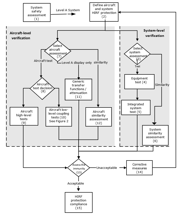
(n) = Step number as described inSection 7 of this AMC
Figure 2: Aircraft low-level coupling tests — Level A
systems
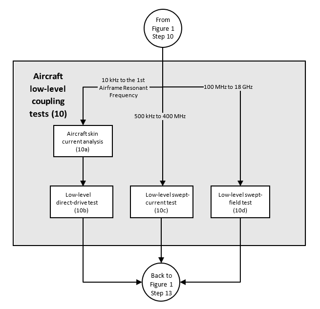
(n) = Step number as described inSection 7 of this AMC
7. STEPS
TO DEMONSTRATE ‘LEVEL A’ SYSTEM HIRF COMPLIANCE
Figures 1 and 2 illustrate a process that the applicant can use to demonstrate that their Level A system complies with CS23.1308(a), 25.1317(a), 27.1317(a), and 29.1317(a).
a. Step
1 — HIRF safety assessment
1. The applicant should determine the system failure condition classification for the systems to be certified on their aircraft, using a system safety assessment as discussed in Section 6(b)(2). For systems classified with catastrophic failure conditions (Level A systems), the applicant should follow compliance steps 2 to 15 listed below, as appropriate. These compliance steps are also depicted in Figures 1 and 2 of this AMC,and are not necessarily accomplished sequentially. Applicants for systems classified with hazardous or major failure conditions (HIRF certification Level B and Level C systems) should follow the compliance steps outlined in Section 8 of this AMC.
2. The system defined for paragraph (a) of CS 23.1308, 25.1317, 27.1317, and 29.1317 is not required to include:
(a) equipment, components and electrical interconnections required only for non-normal situations; or
(b) equipment, components and electrical interconnections required only for dispatching under master minimum equipment lists (MMELs) (when operational suitability data (OSD) is applicable).
3. Some systems include mechanical, hydraulic, and/or pneumatic channels as well as electrical and electronic channel(s) to perform functions whose failure would prevent continued safe flight and landing. The HIRF safety assessment for CS 23.1308(a), 25.1317(a), 27.1317(a), and 29.1317(a) only applies to functions performed by electrical and electronic systems. The HIRF safety assessment should consider electrical or electronic failures that would adversely affect the function of the mechanical, hydraulic, and/or pneumatic channel(s). If electrical or electronic equipment and components, as well as electrical interconnections are used to assist, augment, or monitor for control loop feedback, the mechanical, hydraulic, and/or pneumatic channels in performing the normal operation of the functions with failures that would prevent continued safe flight and landing, then the electrical and electronic channel(s) must comply with CS 23.1308(a), 25.1317(a), 27.1317(a), and 29.1317(a).
4. CS 23.1308(a), 25.1317(a), 27.1317(a), and 29.1317(a) do not require the applicant to assume pre‑existing failure conditions when classifying the functional failure conditions and the scope of Level A systems. The applicant should consider total or partial loss of the systems and malfunctions of the systems, including hazardously misleading information presented to the flight crew during and after the aircraft is exposed to HIRF.
5. CS 23.1308(a)(2), 25.1317(a)(2), 27.1317(a)(2), and 29.1317(a)(2) require that Level A systems automatically recover normal operation of the Level A functions in a timely manner after exposure to HIRF Environment I. Automatic recovery applies to all redundant active channels of the Level A system required for normal operation unless its recovery conflicts with other operational or functional requirements of the system. The exception for automatic recovery conflicts must be based on aircraft operational or functional requirements independent of HIRF exposure. The exception should not be a mitigation for Level A system effects observed after exposure to HIRF Environment I.
6. Appendix 3Examples of HIRF safety assessment considerations — Level A systemsprovides examples of systems’ scope based on the guidance above.
b. Step 2 — Define aircraft and system HIRF protection. The applicant should define the HIRF protection features to be incorporated into the aircraft and system designs, based on the HIRF environments that are applicable to their aircraft and its Level A systems. Equipment, system, and aircraft HIRF protection design may occur before aircraft-level tests are performed, and before the actual internal HIRF environment is determined. Therefore, the equipment, system and aircraft HIRF protection design should be based on an estimate of the expected internal HIRF environment. The applicant should consider all aircraft configurations that may affect HIRF protection, such as open landing gear doors (see Step 7).
c. Step 3 — System assessment decision. The applicant should determine whether to perform integrated system HIRF tests on the Level A system, or to base the system verification on previous integrated system HIRF tests performed on a similar system. Aircraft and system tests and assessments need not be performed for HIRF environments above 18 GHz if data and design analysis show the integrated system test results (see Step 5) satisfy the pass/fail criteria from 12 GHz to 18 GHz, and the systems have no circuits that operate in the 18 GHz to 40 GHz frequency range.
d. Step
4 — Equipment test
1. Radiated and conducted RF susceptibility laboratory tests of RTCA/DO-160G/EUROCAE ED-14G (or latest version) Section 20 may be used to build confidence in the equipment’s HIRF immunity before conducting integrated system laboratory tests in Step 5. The equipment should be specified and tested in accordance with the test levels (wire bundle currents injection and RF field illumination) of RTCA/DO-160/EUROCAE ED-14 Section 20 or to a level estimated for the aircraft and equipment installation using the applicable external HIRF environment.
2. Equipment HIRF tests may be used to augment the integrated system HIRF tests where appropriate. For equipment whose HIRF immunity is evaluated as part of the integrated system-level HIRF tests discussed in Step 5, the individual equipment’s HIRF testing described in this step is optional.
e. Step
5 — Integrated system test
1. Radiated and conducted RF susceptibility laboratory tests on an integrated system should be performed for Level A systems. The HIRF field strengths and wire bundle currents selected for this test should be based on the attenuated external HIRF environment determined in the aircraft assessment (see Steps 10, 11, or 12). In many cases, the integrated system test is performed before the aircraft assessment is complete. In these cases, the integrated system test field strengths and currents should be selected based on the expected aircraft attenuation or transfer function.
2. The installation details for the laboratory integrated system tests should be similar to the installation in the aircraft. For example, the bonding and grounding of the system, wire size, routing, arrangement (whether parallel or twisted wires), connector types, wire shields, and shield terminations, and the relative position of the elements to each other and the ground plane in the laboratory should closely match the system installation on the aircraft to be certified. For this reason, the laboratory integrated system rig should have an Agency conformity inspection prior to conducting any Agency certification credit testing.
3. The integrated system should be tested with the system operating, to include connected displays, sensors, actuators, and other pieces of equipment. Applicants should place the system in various operating modes to ensure the integrated system is tested when operating at its maximum sensitivity. If the connected equipment is not related to the functions with catastrophic failures, these items may be simulated by test sets, if the test sets accurately represent the terminating circuit impedance of the sensor. However, the connected equipment should meet the appropriate HIRF requirements required for its failure condition classification.
4. The test levels should be selected based on the expected aircraft internal HIRF environment determined through aircraft tests (see Step 10), generic transfer functions ‘for Level A display systems only’ and attenuation (see Step 11), or aircraft similarity assessment (see Step 12), using the applicable external HIRF environment. Integrated system test procedures are described in detail in the User’s Guide (SAE ARP 5583A/EUROCAE ED-107A).
5. Wire bundle current injection should be used for frequencies from 10 kHz to 400 MHz. RF currents are injected into the integrated system wiring via a current transformer. Each wire bundle in the system should be injected and the induced wire bundle current measured. If a system wire bundle branches, then each wire bundle branch should also be tested. Simultaneous multi-bundle current injection may be necessary on systems with redundant or multi-channel architectures.
6. High-level radiated susceptibility tests should be used at frequencies greater than 100 MHz. The radiating antenna should be far enough away to ensure the total volume of the equipment and at least half a wavelength of the wiring is simultaneously and uniformly illuminated during the test.
7. The applicant should define appropriate pass/fail criteria for the system, based on the system safety assessment and the appropriate HIRF requirements. Any system susceptibility, including system malfunctions such as displaying hazardously misleading information, upsets, or damage, should be recorded and evaluated based on these previously defined pass/fail criteria.
8. Using only the modulation to which the system under evaluation is most sensitive may minimise the test time. The User’s Guide (SAE ARP 5583A/EUROCAE ED-107A) provides guidance on modulation selection and suggested default modulations and dwell times.
9. The equipment tests in Step 4, using the techniques in RTCA/DO-160G/EUROCAE ED-14G (or latest version) Section 20, normally are not sufficient to show HIRF compliance for Step 5 and Step 6. However, these standard RTCA/DO-160G/EUROCAE ED-14G Section 20 tests may be sufficient if paragraph 7(e)(2) and (3) of this step are met.
10. If the Level A System consists of multiple similar channels, the applicant may propose using one or more channels in the laboratory test set-up for the integrated system, instead of all similar channels. The applicant should demonstrate that the laboratory test set-up adequately performs the functions that must demonstrate compliance with CS 23.1308(a), 25.1317(a), 27.1317(a), and 29.1317(a). The applicant should ensure that the laboratory test set-up represents and monitors any cross-channel interactions, such as cross-channel data links, redundancy management, and system health monitoring.
Note: Similar channels are composed of equipment that has the same hardware but not necessarily the same part number; in case of use of pin programming and/or software to identify or configure equipment of similar channels, it must be assessed whether these differences have an impact on the functions performed.
f. Step
6 — System similarity assessment
1. The integrated system HIRF tests performed for a system previously certified on agiven aircraft model may be used to demonstrate system verification for a similar system. Each system considered under the similarity approach needs to be assessed independently even if it may use equipment and installation techniques from previous certification projects.
2. The system used as the basis for similarity must have successfully completed integrated system HIRF tests. A similarity assessment requires a comparison of both the equipment and installation differences that could adversely affect HIRF immunity. The assessment should evaluate the differences between the previously HIRF certified system and the equipment circuit interfaces, wiring, grounding, bonding, connectors, and wire-shielding practices of the equipment that is part of the new system.
3. If the assessment finds only minimal differences between the previously certified system and the new system to be certified, similarity may be used as the basis for system-level verification without the need for additional integrated system tests, provided there are no unresolved in-service HIRF problems related to the previously certified system. If there is uncertainty about the effects of the differences, additional tests and analyses should be conducted, as necessary and appropriate, to resolve the uncertainty. The amount of additional testing should be commensurate with the degree of difference identified between the new system and the system previously certified. If significant differences are found, similarity should not be used as the basis for system-level verification.
g. Step
7 — Aircraft assessment decision
1. Level A systems require an aircraft assessment. The aircraft assessment should determine the actual internal HIRF environment where the Level A systems are installed in the aircraft. The applicant should choose whether to use aircraft tests, previous coupling/attenuation data from similar aircraft types (similarity). For Level A display systems only, applicants should use the generic transfer functions and attenuation in Appendix 1 to this AMC. Alternately, the aircraft assessment may be a test that exposes the entire aircraft with operating Level A systems to external HIRF Environment I, II, or III (Tables 2, 3, and 4 respectively), as appropriate, to demonstrate acceptable Level A system performance.
2. Level A display systems include the display equipment, control panels, and the sensors that provide information to the displays. These sensors could also provide information to Level A non-display systems, so in that case, the applicant should determine the real transfer function and attenuation curves of these sensors when demonstrating compliance for this Level A non-display system. For example, for air data systems and inertial reference systems, which send information to the EFIS and flight controls, the transfer function and attenuation should be determined by aircraft low-level coupling testing or an aircraft similarity assessment as defined in Steps 10 and 12.
3. Other methods for aircraft HIRF assessment, such as analysis, may be acceptable. However, comprehensive modelling and analysis for RF field coupling to the aircraft structure is an emerging technology. Therefore, analysis alone is currently not adequate to show HIRF compliance for Level A systems and should be augmented by testing.
4. If analysis is used to determine aircraft attenuation and transfer function characteristics, test data should be provided to support this analysis. Any analysis results should take into account the quality and accuracy of the analysis. Significant testing, including aircraft-level testing, may be required to support the analysis.
5. Aircraft and system tests and assessments need not be performed for the HIRF environments above 18 GHz if data and design analysis show the integrated system test results (see Step 5) satisfy the pass/fail criteria from 12 to 18 GHz, and the systems have no circuits operating in the 18 to 40 GHz frequency range.
h. Step
8 — Aircraft test decision
1. Various aircraft test procedures are available and accepted for collecting data for aircraft HIRF verification. The two main approaches to aircraft testing are the aircraft high-level test (see Step 9) and the aircraft low-level coupling test (see Step 10). The aircraft high-level field-illumination test involves radiating the aircraft at test levels equal to the applicable external HIRF environment in the HIRF requirements. Aircraft low-level coupling tests involve measuring the airframe attenuation and transfer functions, so that the internal HIRF electric fields and currents can be compared with the integrated system test levels.
2. Some test procedures may be more appropriate than others because of the size of the aircraft and the practicality of illuminating the entire aircraft with the appropriate external HIRF environment. The aircraft low-level coupling tests (see Step 10) may be more suitable for testing large aircraft than the high-level field-illumination test in Step 9, which requires illumination of the entire aircraft with the external HIRF environment.
i. Step
9 — Aircraft high-level tests
1. The aircraft high-level field-illumination test requires generating RF fields external to an aircraft at a level equal to the applicable external HIRF environment.
2. At frequencies below 400 MHz, the distance between the aircraft and the transmitting antenna should be sufficient to ensure the aircraft is illuminated uniformly by the external HIRF environment. The transmitting antenna should be placed in at least four positions around the aircraft. For aircraft, the antenna is typically placed to illuminate the nose, tail, and each wingtip. For rotorcraft, the antenna is typically placed to illuminate the nose, tail, and each side. The aircraft should be illuminated by the antenna at each position while sweeping the frequency range. Perform separate frequency sweeps with the transmitting antenna oriented for horizontal and vertical polarisation. The RF field should be calibrated by measuring the RF field strength in the centre of the test volume before the aircraft is placed there.
3. At frequencies above 400 MHz, the RF illumination should be localised to the system under test, provided all parts of the system and at least one wavelength of any associated wiring (or the total length if less than one wavelength) are illuminated uniformly by the RF field. The applicant may need reflection planes to illuminate relevant apertures on the bottom and top of the aircraft.
4. To ensure the systems are tested when operating at their maximum sensitivity, Level A systems should be fully operational, and the aircraft should be placed in various simulated operating modes.
5. The test time can be minimised by using only the modulation to which the system under evaluation is most sensitive. If the applicant does this, the rationale used to select the most sensitive modulation should be documented in the HIRF test plan as discussed in Section 6(b)(1). The User’s Guide (SAE ARP 5583A/EUROCAE ED-107A) provides guidance on modulation selection and suggested default modulations and dwell times.
6. As an alternative to testing at frequencies below the first airframe resonant frequency, it is possible to inject high-level currents directly into the airframe using aircraft high-level direct-drive test methods. Aircraft skin current analysis should be performed as described in the User’s Guide, or low-level swept‑current measurements should be made to determine the skin current distribution that will exist for different RF field polarisations and aircraft illumination angles so that these can be simulated accurately during this test. Aircraft high-level direct-drive testing, although applicable only from 10 kHz to the first airframe resonant frequency, is advantageous because it is possible to test all systems simultaneously.
j. Step
10 — Aircraft low-level coupling tests
1. General
(a) The aircraft low-level coupling tests include three different tests that cover the frequency range of 10 kHz to 18 GHz (see Figure 2). Detailed descriptions are available in the User’s Guide. Other techniques may be valid, but must be discussed with and accepted by the Agency before being used.
(b) The low-level direct-drive test (see Step 10b, Figure 2) and the low-level swept-current test (see Step 10c) are used for frequencies at or below 400 MHz. The low-level swept-field test (see Step 10d) is used for frequencies at and above 100 MHz. There is an overlap of test frequencies from 100 to 400 MHz in the low-level swept-current test and the low-level swept-field test. The division at 100 MHz is not absolute and depends on the aircraft to be tested and the resonance of the wiring and instrumentation limitations. The division at 400 MHz is not absolute either, and depends on when HIRF penetration of the equipment case becomes a significant factor.
2. Steps 10a and 10b — Aircraft skin current analysis and low-level direct-drive test. Low-level direct‑drive tests in conjunction with skin current analysis should be used to determine the transfer function between the skin current and individual equipment wire bundle currents. The low-level direct‑drive test is typically used for frequencies from 10 kHz to the first airframe resonant frequency. For the low-level direct-drive test to be applied successfully, a three-dimensional model of the aircraft should be derived using aircraft skin current analysis. The three-dimensional model can then be used to derive the aircraft’s skin current pattern for the applicable external HIRF environment. Guidance on skin current analysis is in the User’s Guide. If the relationship between the external HIRF environment and the skin current is known for all illumination angles and polarisation, either because of aircraft skin current analysis or the use of the low-level swept-current test, the skin current can be set up by direct injection into the airframe. The resultant currents on the system wire bundles are measured with a current probe and normalised to 1 V/m electric field strength so they can be scaled to the appropriate external HIRF environment. The low-level direct-drive test is more effective than low-level swept‑current tests for frequencies from 10 kHz to the first airframe resonant frequency, and may be necessary for small aircraft or aircraft with high levels of airframe shielding.
3. Step 10c — Low-level swept-current test. The low-level swept-current test involves illuminating the aircraft with a low-level external HIRF field to measure the transfer function between the external field and the aircraft and equipment wire bundle currents. This test is typically used in the frequency range of 500 kHz to 400 MHz. The transfer function is resonant in nature and is dependent on both the aircraft structure and the system installation. Because the transfer function relates wire bundle currents to the external field, the induced bulk current injection test levels can be related to an external HIRF environment.
The transmitting antenna should be placed in at least four positions around the aircraft, with the distance between the aircraft and the transmitting antenna sufficient to ensure the aircraft is illuminated uniformly. For aircraft, the antenna is typically placed to illuminate the nose, tail, and each wingtip. For rotorcraft, the antenna is typically placed to illuminate the nose, tail, and each side. The aircraft should be illuminated by the antenna at each position while sweeping the frequencies in the range of 500 kHz to 400 MHz. The applicant should perform separate frequency sweeps with the transmitting antenna oriented for horizontal and vertical polarisation, and measure the currents induced on the aircraft wire bundles.
The applicant should calculate the ratio between the induced wire bundle current and the illuminating antenna field strength, and normalise this ratio to 1 V/m. This provides the transfer function in terms of induced current per external field strength unit. Then the current induced by the applicable external HIRF environment can be calculated by multiplying the transfer function by the external HIRF field strength. The calculated HIRF currents for all transmitting antenna positions for each aircraft wire bundle to beassessed should be overlaid to produce worst-case induced current for each wire bundle. These worst-case induced currents can be compared with the current used during the integrated system test in Step 5.
4. Step 10d — Low-level swept-field test. Low-level swept-field testing is typically used from 100 MHz to 18 GHz. The test procedures for the low-level swept-field test are similar to those used for the low-level swept-current test; however, in the low-level swept-field test, the internal RF fields in the vicinity of the equipment are measured instead of the wire bundle currents. Various techniques can be used to ensure the maximum internal field in the vicinity of the equipment is measured. Depending on the size of the aircraft and the size of the aircraft cabin, flight deck, and equipment bays, multipoint measurement or mode stirring can be used to maximise the internal field in the vicinity of the equipment. See the User’s Guide (SAE ARP 5583A/EUROCAE ED-107A) for detailed low-level swept-field test procedures.
k. Step
11 — Generic transfer functions and attenuation — Level A display systems only
1. Level A displays involve functions for which system information is displayed directly to the pilot. For Level A display systems, the aircraft attenuation data may be determined using generic attenuation and transfer function data. This approach should not be used for other Level A systems, such as control systems, because failures and malfunctions of those systems can more directly and abruptly contribute to a catastrophic failure event than display system failures and malfunctions; therefore, other Level A systems should have a more rigorous HIRF compliance verification programme.
2. The integrated system test levels specified in Step 5 may be derived from the generic transfer functions and attenuation for different types of aircraft. Acceptable transfer functions for calculating the test levels are given in Appendix 1 to this AMC.Appendix 1 to this AMC also contains guidelines for selecting the proper generic attenuation. The generic transfer functions show the envelope of the currents that might be expected to be induced in the types of aircraft in an external HIRF environment of 1 V/m. The current levels should be multiplied linearly by HIRF Environment I, II, or III, as appropriate, to determine the integrated system test levels.
3. The internal HIRF electric field levels are the external HIRF environment divided by the appropriate attenuation, in linear units. For example, 20 dB or a 10:1 attenuation means the test level is the applicable external HIRF environment electric field strength reduced by a factor of 10.
4. The internal HIRF environments for Level A display systems can also be measured using on-aircraft low‑level coupling measurements of the actual system installation (see Step 10). This procedure should provide more accurate information to the user, and the test levels may be lower than the generic transfer functions or attenuation, which are worst-case estimates.
l. Step
12 — Aircraft similarity assessment
1. The aircraft attenuation and transfer function tests performed for a previously certified aircraft may be used to support aircraft-level verification for a similar aircraft model. The aircraft used as the basis for similarity must have been previously certified for HIRF compliance, using HIRF attenuation and transfer functions determined by tests on that aircraft.
2. The similarity assessment for the new aircraft model should consider the aircraft differences that could impact on the internal HIRF environment affecting the Level A systems and the associated wiring. The comparison should consider equipment and wiring locations, airframe materials and construction, and apertures that could affect attenuation for the external HIRF environment.
3. If the assessment finds only minimal differences between the previously certified aircraft and the new aircraft to be certified, similarity may be used to determine the aircraft attenuation and transfer functions without the need for additional aircraft tests, providing there are no unresolved in-service HIRF problems related to the existing aircraft. If there is uncertainty about the effects of the differences, additional tests and analyses should be conducted as necessary and appropriate to resolve the uncertainty. The amount of additional testing should be commensurate with the degree of difference identified between the new aircraft to be certified and the aircraft previously certified. If significant differences are found, similarity should not be used as the basis for aircraft-level verification.
m. Step
13 — Assess the immunity
1. The applicant should compare the test levels used for the integrated system test of Step 5 with the internal RF current or RF fields determined by the aircraft low-level coupling tests (see Step 10), the generic transfer functions and attenuation (see Step 11), or the aircraft similarity assessment (see Step 12). The actual aircraft internal RF currents and RF fields should be lower than the integrated system test levels.The comparison method should be included in the HIRF compliance plan. The method should enable a direct comparison between the system test level and the aircraft internal HIRF environment at the equipment or system location, using current for frequencies from 10 kHz to 400 MHz, and using electric field strength for frequencies from 100 MHz through 18 GHz.
2. If the conducted RF susceptibility test levels used for the integrated system test (see Step 5) were too low when compared with the aircraft-induced currents determined in Steps 10b, 10c, 11 or 12, then corrective measures are needed (see Step 14). If the radiated RF susceptibility test levels used for integrated system tests (see Step 5) were too low when compared with the aircraft internal fields determined in Steps 10d, 11 or 12, then corrective measures are needed (see Step 14).
3. When comparing the current measured during low-level swept-current tests in Step 10c with the current used during the integrated system tests in Step 5, there may be differences. These differences may be due to variations between the actual aircraft installation and the integrated system laboratory installation, such as wire bundle lengths, shielding and bonding, and wire bundle composition. The worst-case current signature for a particular wire bundle should be compared with the current induced at the particular test level or equipment malfunction over discrete frequency ranges such as 50 to 500 kHz, 500 kHz to 30 MHz, and 30 to 100 MHz. This comparison should be broken into discrete frequency ranges because the resonant frequencies may differ between the integrated system tests and the aircraft tests.
4. If the applicant uses aircraft high-level tests (see Step 9) for aircraft HIRF verification, they should determine whether there were any Level A system susceptibilities. Any Level A system susceptibilities should be evaluated based on the pass/fail criteria as established in the test plan (see Section 8(b)(1)). If the HIRF susceptibilities are not acceptable, then corrective measures may be needed (seeStep 14).
5. HIRF susceptibilities that were not anticipated or defined in the test plan pass/fail criteria may be observed during aircraft high-level tests or integrated system laboratory tests. The pass/fail criteria may be modified if the effects neither cause nor contribute to conditions that adversely affect the aircraft functions or systems in the HIRF requirements. The applicant should provide an assessment and the supporting rationale for any modifications to the pass/fail criteria to the Agency for acceptance.
If the HIRF susceptibilities are not acceptable, then corrective measures may be needed (see Step 14).
6. If the Level A systems show no adverse effects when tested to levels derived from the applicable HIRF Environment I or III, this also demonstrates compliance of the system with HIRF Environment II.
7. If the integrated system test results (see Step 5) satisfy the pass/fail criteria from 12 to 18 GHz, and design analysis shows the system has no circuits operating in the 18 to 40 GHz frequency range, this demonstrates by analysis that the system is not adversely affected when exposed to HIRF environments above 18 GHz. If these conditions are satisfied, further aircraft and system tests and assessments above 18 GHz are not necessary.
8. The applicant should review the actual system installation in the aircraft and the system configuration used for the integrated system test (see Step 5). If significant configuration differences are identified, corrective measures may be needed (see Step 14).
9. Certain RF receivers with antennas connected should not be expected to perform without effects during exposure to the HIRF environments, particularly in the RF receiver operating band. Because the definition of adverse effects and the RF response at particular portions of the spectrum depends on the RF receiver system function, the applicant should refer to the individual RF receiver minimum performance standards for additional guidance. However, because many RF receiver minimum performance standards were prepared before the implementation of the HIRF requirements, the RF receiver pass/fail criteria should be coordinated with the Agency.
10. The applicant should provide the similarity assessment and the supporting rationale to the Agency for acceptance.
n. Step 14 — Corrective measures. Corrective measures should be taken if the system fails to satisfy the HIRF immunity assessment of Step 13. If changes or modifications to the aircraft, equipment, system or system installation are required, then additional tests may be necessary to verify the effectiveness of the changes. The RTCA/DO-160G/EUROCAE ED-14G, or latest version, Section 20 equipment tests, integrated system tests, and aircraft tests, in whole or in part, may need to be repeated to show HIRF compliance.
o. Step 15 — HIRF protection compliance. The test results and compliance report should be submitted to the Agency for approval as part of the overall aircraft type certification or supplemental type certification process.
Figure 3: Routes to HIRF compliance — Level B and Level
C systems
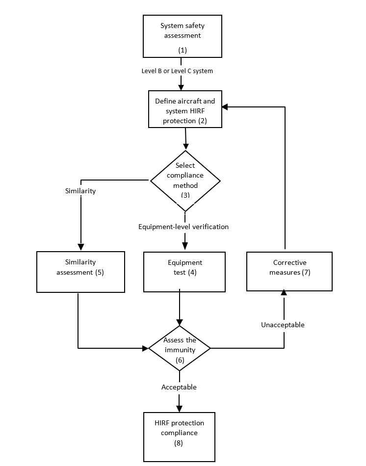
(n) = Step number as described in Section 10 of this AMC
8. STEPS
TO DEMONSTRATE ‘LEVEL B’ AND ‘LEVEL C’ SYSTEM HIRF COMPLIANCE
Figure 3 illustrates a process that the applicant can use to demonstrate whether their Level B and Level C systems comply with CS23.1308(b), 25.1317(b), 27.1317(b), and 29.1317(b), and with CS 23.1308(c), 25.1317(c), 27.1317(c), and 29.1317(c) respectively.
a. Step 1 — HIRF safety assessment. The applicant should determine the system certification level for the systems to be certified on their aircraft, using a system safety assessment as discussed in Section 6(b)(2). For systems classified with hazardous or major failure conditions (Level B and Level C systems), the applicant should follow compliance Steps 2 through 8 listed below, as appropriate. These compliance steps are also depicted in Figure 3 of this AMC and are not necessarily accomplished sequentially. For systems classified with catastrophic failure conditions (Level A systems), the applicant should follow the compliance steps outlined in Section 7.
b. Step 2 — Define the aircraft and system HIRF protection. The applicant should define the HIRF protection features incorporated into the aircraft and system designs, based on the HIRF test levels applicable to their aircraft and its Level B and Level C systems. Equipment, system, and aircraft HIRF protection design may occur before aircraft-level tests are performed, and before the actual internal HIRF environment is determined. Therefore, the equipment, system and aircraft HIRF protection design should be based on an estimate of the expected internal HIRF environment.
c. Step 3 — Select the compliance method. The applicant should determine whether to perform equipment HIRF tests on the Level B and Level C systems, or to base the compliance on previous equipment tests performed for a similar system.
d. Step 4 — Equipment test
1. Level B and Level C systems do not require the same degree of HIRF compliance testing as Level A systems and, therefore, do not require aircraft-level testing. RTCA/DO-160G/EUROCAE ED-14G,or latest version, Section 20 laboratory test procedures should be used, using equipment test levels defined in the applicable specifications. The test levels used depend on whether the system is categorised as Level B or Level C. Equipment HIRF test Level 1 or 2, as applicable, should be used for Level B systems. RTCA/DO‑160/EUROCAE ED-14 Section 20 Category RR (using the alternative modulation for radiated susceptibility) satisfies the requirements of equipment HIRF test Level 1. For equipment HIRF test Level 2, the applicant may use the approach in Section 9(k) to help determine the acceptable aircraft transfer function and attenuation curves for their Level B system. Equipment HIRF test Level 3 should only be used for Level C systems. RTCA/DO-160/EUROCAE ED-14 Section 20 Category TT satisfies the requirements of equipment HIRF test Level 3. When applying modulated signals, the test levels are given in terms of the peak of the test signal as measured by a rootmeansquare (rms), indicating the spectrum analyser’s peak detector. See the User’s Guide (SAE ARP 5583A/EUROCAE ED‑107A) for more details on modulation.
2. The applicant should define appropriate pass/fail criteria for the system, based on the system safety assessment and the appropriate HIRF requirements (see Section 6(b)(2)). Any susceptibility noted during the equipment tests, including equipment malfunctions, upsets, or damage, should be recorded and evaluated based on the defined pass/fail criteria.
e. Step 5 — Similarity assessment
1. The equipment HIRF tests performed for a system previously certified on a given aircraft model may be used to show compliance for a similar system. Each system considered for similarity needs to be assessed independently even if it used equipment and installation techniques from a previous certification.
2. The system used as the basis for certification by similarity must have successfully completed equipment HIRF tests and been previously certified for HIRF compliance on another aircraft model. Similarity assessment requires a comparison of both the equipment and installation differences that could adversely affect HIRF immunity. An assessment of a new system should consider the differences in the equipment circuit interfaces, wiring, grounding, bonding, connectors, and wire-shielding practices.
3. If the assessment finds only minimal differences between the previously certified system and the new system to be certified, similarity may be used for HIRF compliance without the need for additional equipment HIRF tests, provided there are no unresolved in-service HIRF problems related to the previously certified system. If there is uncertainty about the effects of the differences, additional tests and analyses should be conducted as necessary and appropriate to resolve the uncertainty. The amount of additional testing should be commensurate with the degree of difference identified between the new system and the system previously certified. If significant differences are found, similarity should not be used as the basis for HIRF compliance.
f. Step 6 — Assess the immunity
1. The applicant should review the results of the equipment test to determine whether the pass/fail criteria are satisfied. HIRF susceptibilities that were not anticipated or defined in the test plan pass/fail criteria may be observed during equipment HIRF tests. The pass/fail criteria may be modified if the effects neither cause nor contribute to conditions that adversely affect the aircraft functions or systems, as applicable, in the HIRF requirements. The applicant should provide an assessment of, and the supporting rationale for, any modifications to the pass/fail criteria to the Agency for approval. If the HIRF susceptibilities are not acceptable, then corrective measures may be needed (see Step 7).
2. The applicant should review the actual system installation in the aircraft and the configuration used for the equipment tests (see Step 4). If significant differences in grounding, shielding, connectors, or wiring are identified, corrective measures may be needed (see Step 7).
3. Certain RF receivers with antennas connected should not be expected to perform without effects during exposure to the HIRF environments, particularly in the RF receiver operating band. Because the definition of adverse effects and the RF response at particular portions of the spectrum depends on the RF receiver system function, applicants should refer to the individual RF receiver minimum performance standards for additional guidance. However, because many RF receiver minimum performance standards were prepared before the implementation of the HIRF requirements, the RF receiver pass/fail criteria should be coordinated with the Agency. Future modifications of the minimum performance standards should reflect the HIRF performance requirements.
g. Step 7 — Corrective measures. The applicant should take corrective measures if the system fails to satisfy the HIRF immunity assessment of Step 6. If changes or modifications to the equipment, system, or system installation are required, then additional tests may be necessary to verify the effectiveness of the changes. The RTCA/DO-160G/EUROCAE ED-14G,or latest version, Section 20 equipment tests, in whole or in part, may need to be repeated to show HIRF compliance.
h. Step 8 — HIRF protection compliance. The applicant shouldsubmit the test results and compliance report to the Agency for acceptance as part of the overall aircraft type certification or supplemental type certification process.
9. HIRF
COMPLIANCE DEMONSTRATION
a. HIRF compliance plan. An overall HIRF compliance plan should be established to clearly identify and define HIRF certification requirements, HIRF protection development, and the design, test, and analysis activities intended to be part of the compliance effort. This plan should provide definitions of the aircraft systems, installations, and protective features against which HIRF compliance will be assessed. The HIRF compliance plan should be discussed with, and submitted to, the Agency for acceptance before initiating HIRF compliance activities. If the aircraft, system, or installation design changes after approval, a revised HIRF compliance plan should be submitted to the Agency for acceptance. The HIRF compliance plan should include the following:
1. a HIRF compliance plan summary;
2. identification of the aircraft systems, with classifications based on the safety assessment as it relates to HIRF (seeSection 6(b)(2));
3. the planned or expected HIRF environment for the aircraft and installed systems; and
4. the verification methods, such as test, analysis, or similarity.
b. Methods of compliance verification
1. Various methods are available to aid in demonstrating HIRF compliance. Methods acceptable to the Agency are described in Sections 6 and 7 of this AMC. Figures 1 and 2 above outline the steps to HIRF compliance for systems that requireLevel A HIRF certification. Figure 3 above outlines the steps to HIRF compliance for systems that require Level B or Level C HIRF certification. The steps in these figures are not necessarily accomplished sequentially. Wherever a decision point is indicated on these figures, the applicant should complete the steps in that path as described in Sections 6 and 7 of this AMC.
2. Other HIRF compliance techniques may be used to demonstrate system performance in the HIRF environment; however, those techniques should be accepted by the Agency before using them.
c. HIRF verification test, analysis, or similarity plan. Test, analysis and similarity are all acceptable methods. The applicant must choose the method or the combination of methods most appropriate for their project. See Sections 6 and 7 of this AMC, and SAE ARP 5583A/EUROCAE ED-107A for additional guidance for selecting the appropriate method. Specific HIRF test, analysis, or similarity plans could be prepared to describe specific verification activities. A single verification plan combining various methods for all the selected systems or dedicated verification plans may be necessary. For example, there may be several systems or equipment laboratory test plans, an aircraft test plan, or a similarity plan for selected systems on an aircraft.
1. Test
plan
(a) A HIRF compliance test plan may include the equipment, system, and aircraft test objectives for the acquisition of data to support HIRF compliance verification. The plan should provide an overview of the factors to be addressed for each system testrequirement.
The test plan should include:
1. the purpose of the test;
2. a description of the aircraft and/or the system to be tested;
3. system configuration drawings;
4. the proposed test set-up and methods;
5. the intended test levels, modulations, and frequency bands;
6. pass/fail criteria; and
7. the test schedule and test location.
(b) The test plan should cover Level A, B, and C systems and equipment, as appropriate. Level A systems may require both integrated systems laboratory tests and aircraft tests. Level B and Level C systems and equipment require only equipment laboratory testing.
(c) The test plan should describe the appropriate aspects of the systems to be tested and their installation. Additionally, the test plan should reflect the results of any analysis performed in the overall process of the HIRF compliance evaluation.
2. Analysis plan. A HIRF compliance analysis plan should include the objectives, both at system and equipment level, for generating data to support HIRF compliance verification. Comprehensive modelling and analysis for RF field coupling to aircraft systems and structures is an emerging technology; therefore, the analysis plan should be coordinated with the Agency to determine an acceptable scope for the analysis.
The analysis plan should include:
(a) the purpose and scope of the analysis;
(b) a description of the aircraft and/or the system addressed by the analysis;
(c) system configuration descriptions;
(d) the proposed analysis methods;
(e) the approach for validating the analysis results; and
(f) pass/fail criteria, including margins to account for analysis uncertainty.
3. Similarity plan. A similarity plan should describe the approach undertaken to use the certification data from previously certified systems, equipment, and aircraft in the proposed HIRF compliance programme.
The similarity plan should include:
(a) the purpose and scope of the similarity assessment;
(b) the specific systems addressed by the similarity assessment;
(c) the data used from the previously certified systems, equipment, and aircraft;
(d) details of the significant differences between the aircraft and system to becertified and the similar aircraft and system from which the data will be used; and
(e) when data has limited substantiation, a description and justification for margins to account for similarity uncertainty;see Section 6(f)(3) for additional information on margins.
d. Compliance reports. One or more compliance reports may be necessary to document the results of test, analysis, or similarity assessments. For new or significantly modified aircraft, HIRF compliance reports include many system and equipment test reports, aircraft test reports, and HIRF vulnerability analysis reports. For these types of HIRF certification programmes, a compliance summary report may be useful to summarise the results of tests and analyses. For HIRF certification programmes of relatively simple systems, a single compliance report is adequate.
1. Test reports. Comprehensive test reports should be produced at the conclusion of HIRF compliance testing. The test reports should include descriptions of the salient aspects of equipment or system performance during the test, details of any area of non-compliance with HIRF requirements, actions taken to correct the non-compliance, and any similarity declarations. The applicant should also provide the supporting rationale for any deviations from system performance observed during testing.
2. Analysis reports. Analysis reports should describe the details of the analytical model, the methods used to perform the analysis, and the results of the analysis. The reports should identify any modelling uncertainty and justify the margins established in the analysis plan.
3. Similarity reports. Similarity reports should document the significant aircraft, system, equipment, and installation features that are common between the aircraft or system that is the subject of the similarity analysis and the aircraft or system that was previously certified for HIRF. The reports should identify all the significant differences encountered, along with the assessment of the impact of these differences on HIRF compliance. These reports should also justify the margins established in the similarity plan.
10. MAINTENANCE,
PROTECTION ASSURANCE, AND MODIFICATIONS
a. The minimum maintenance required to support HIRF certification should be identified in the instructions for continued airworthiness (ICAs) as specified in CS 23.1529, 25.1529, 25.1729, 27.1529, and 29.1529, as appropriate. Dedicated devices or specific features may be required to provide HIRF protection for an equipment or system installation. Appropriate maintenance procedures should be defined for these devices and features to ensure in-service protection integrity. A HIRF protection assurance programme should be proposed in the certification plan to identify all actions necessary to justify or to verify that the maintenance procedures are adequate. This assurance programme may propose a surveillance programme based on a sampling of the fleet for monitoring the effectiveness of the protection features and/or maintenance procedures. The User’s Guide (SAE ARP 5583A/EUROCAE ED107A) provides further information on these topics.
b. The maintenance procedures should consider the effects of corrosion, fretting, flexing cycles, or other causes that could degrade these HIRF protection devices. Whenever applicable, specific replacement times of these devices and features should be identified.
c. Aircraft or system modifications should be assessed for the impact that any changes will have on the HIRF protection. This assessment should be based on analysis and/or measurement.
[Amdt 20/23]