Light
Dark
System
Log In
Loading...
Compare / EASA/
Incorporated Amendments
/
Compare & Highlight Differences
CS ADR-DSN.M.745 Runway guard lights
Available versions for ERULES-1963177438-2296
ED Decision 2022/006/R
found in: Aerodromes (No 139/2014) Part-ADR.AR Part-ADR.OR Part-ADR.OPS CS-ADR-DSN CS-HPT-DSN (Jun 2023)
Select original version
...24)
...23)
Original Text
Select changed version
...24)
...23)
Changed text
Removed: 0
Added: 0
Unchanged: 0
Share
CS ADR-DSN.M.745 Runway guard lights ED Decision 2022/006/R (a) The safety objective of the runway guard lights is to warn pilots and drivers of vehicles, when operating on taxiways, that they are about to enter arunway. There are two standard configurations of runway guard lights as illustrated in Figure M-12. (b) Applicability: (1) Runway guard lights, Configuration A, should be provided at each taxiway/runway intersection associated with a runway intended for use in: (i) runway visual range conditions less than a value of 550 m where a stop bar is not installed; and (ii) runway visual range conditions of values between 550 m and 1 200 m where the traffic density is heavy. (2) As part of runway incursion prevention measures, runway guard lights, Configuration A or B, should be provided at each taxiway/runway intersection where runway incursion hot spots have been identified, and used under all weather conditions during day and night. (3) Configuration B runway guard lights should not be collocated with a stop bar. (4) Where more than one runway-holding position exists at a runway/taxiway intersection, only the set of runway guard lights associated with the operational runway-holding position should be illuminated. (c) Location: (1) Runway guard lights, Configuration A, should be located at each side of the taxiway within the area delimited by the inner and the outer edges of the runway holding position marking. (2) Runway guard lights, Configuration B, should be located across the taxiway within the area delimited by the inner and the outer edges of the runway holding position marking. (d) Characteristics: (1) Runway guard lights, Configuration A, should consist of two pairs of yellow lights. (2) Runway guard lights, Configuration B, should consist of yellow lights spaced at intervals of 3 m across the taxiway. (3) The light beam should be unidirectional and should show yellow in the direction of approach to the runway-holding position. (4) The intensity in yellow light and beam spreads of lights of Configuration A should be in accordance with the specifications in [CS ADR-DSN.U.940](#_DxCrossRefBm1800047367), Figure U-27. (5) Where runway guard lights are intended for use during the day, the intensity in yellow light and beam spreads of lights of Configuration A should be in accordance with the specifications in [CS ADR-DSN.U.940](#_DxCrossRefBm1800047367), Figure U-28. (6) Where runway guard lights are specified as components of an advanced surface movement guidance and control system where higher light intensities are required, the intensity in yellow light and beam spreads of lights of Configuration A should be in accordance with the specifications in [CS ADR-DSN.U.940](#_DxCrossRefBm1800047367), Figure U-28. (7) The intensity in yellow light and beam spreads of lights of Configuration B should be in accordance with the specifications in [CS ADR-DSN.U.940](#_DxCrossRefBm1800047367), Figure U-28. (8) Where runway guard lights are intended for use during the day, the intensity in yellow light and beam spreads of lights of Configuration B should be in accordance with the specifications in [CS ADR-DSN.U.940](#_DxCrossRefBm1800047367), Figure U-24. (9) Where runway guard lights are specified as components of an advanced surface movement guidance and control system where higher light intensities are required, the intensity in yellow light and beam spreads of lights of Configuration B should be in accordance with the specifications in [CS ADR-DSN.U.940](#_DxCrossRefBm1800047367), Figure U-24. (10) The lights in each unit of Configuration A should be illuminated alternately. (11) For Configuration B, adjacent lights should be alternately illuminated and alternative lights should be illuminated in unison. (12) The lights should be illuminated between 30 and 60 cycles per minute and the light suppression and illumination periods should be equal and opposite in each light. (13) Runway guard lights chromaticity should be in accordance with the specifications in [CS ADR-DSN.U.930](#_DxCrossRefBm1800047721) and Figure U-1A or U-1B, as appropriate.  Figure M-12. Runway guard lights [Issue: ADR-DSN/3] [Issue: ADR-DSN/4] [Issue: ADR-DSN/6]
CS ADR-DSN.M.745 Runway guard lights ED Decision 2022/006/R (a) The safety objective of the runway guard lights is to warn pilots and drivers of vehicles, when operating on taxiways, that they are about to enter arunway. There are two standard configurations of runway guard lights as illustrated in Figure M-12. (b) Applicability: (1) Runway guard lights, Configuration A, should be provided at each taxiway/runway intersection associated with a runway intended for use in: (i) runway visual range conditions less than a value of 550 m where a stop bar is not installed; and (ii) runway visual range conditions of values between 550 m and 1 200 m where the traffic density is heavy. (2) As part of runway incursion prevention measures, runway guard lights, Configuration A or B, should be provided at each taxiway/runway intersection where runway incursion hot spots have been identified, and used under all weather conditions during day and night. (3) Configuration B runway guard lights should not be collocated with a stop bar. (4) Where more than one runway-holding position exists at a runway/taxiway intersection, only the set of runway guard lights associated with the operational runway-holding position should be illuminated. (c) Location: (1) Runway guard lights, Configuration A, should be located at each side of the taxiway within the area delimited by the inner and the outer edges of the runway holding position marking. (2) Runway guard lights, Configuration B, should be located across the taxiway within the area delimited by the inner and the outer edges of the runway holding position marking. (d) Characteristics: (1) Runway guard lights, Configuration A, should consist of two pairs of yellow lights. (2) Runway guard lights, Configuration B, should consist of yellow lights spaced at intervals of 3 m across the taxiway. (3) The light beam should be unidirectional and should show yellow in the direction of approach to the runway-holding position. (4) The intensity in yellow light and beam spreads of lights of Configuration A should be in accordance with the specifications in [CS ADR-DSN.U.940](#_DxCrossRefBm151830505), Figure U-27. (5) Where runway guard lights are intended for use during the day, the intensity in yellow light and beam spreads of lights of Configuration A should be in accordance with the specifications in [CS ADR-DSN.U.940](#_DxCrossRefBm151830505), Figure U-28. (6) Where runway guard lights are specified as components of an advanced surface movement guidance and control system where higher light intensities are required, the intensity in yellow light and beam spreads of lights of Configuration A should be in accordance with the specifications in [CS ADR-DSN.U.940](#_DxCrossRefBm151830505), Figure U-28. (7) The intensity in yellow light and beam spreads of lights of Configuration B should be in accordance with the specifications in [CS ADR-DSN.U.940](#_DxCrossRefBm151830505), Figure U-28. (8) Where runway guard lights are intended for use during the day, the intensity in yellow light and beam spreads of lights of Configuration B should be in accordance with the specifications in [CS ADR-DSN.U.940](#_DxCrossRefBm151830505), Figure U-24. (9) Where runway guard lights are specified as components of an advanced surface movement guidance and control system where higher light intensities are required, the intensity in yellow light and beam spreads of lights of Configuration B should be in accordance with the specifications in [CS ADR-DSN.U.940](#_DxCrossRefBm151830505), Figure U-24. (10) The lights in each unit of Configuration A should be illuminated alternately. (11) For Configuration B, adjacent lights should be alternately illuminated and alternative lights should be illuminated in unison. (12) The lights should be illuminated between 30 and 60 cycles per minute and the light suppression and illumination periods should be equal and opposite in each light. (13) Runway guard lights chromaticity should be in accordance with the specifications in [CS ADR-DSN.U.930](#_DxCrossRefBm151830859) and Figure U-1A or U-1B, as appropriate. 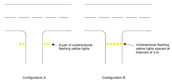 Figure M-12. Runway guard lights [Issue: ADR-DSN/3] [Issue: ADR-DSN/4] [Issue: ADR-DSN/6]