Light
Dark
System
Log In
Loading...
Compare / EASA/
Incorporated Amendments
/
Compare & Highlight Differences
AMC 20-170 Integrated modular avionics (IMA)
Available versions for ERULES-1963177438-10286
ED Decision 2018/008/R
found in: AMC-20 Amdt 21 - Airworthiness of Products, Parts and Appliances (Apr 2021)
Select original version
...21)
...22)
...21)
Original Text
Select changed version
...21)
...22)
...21)
Changed text
Removed: 0
Added: 0
Unchanged: 0
Share
AMC 20-170 Integrated modular avionics (IMA) ED Decision 2018/008/R 1. Introduction 1.1. Purpose This Acceptable Means of Compliance (AMC) provides a means that can be used to demonstrate that the safety aspects of integrated modular avionics (IMA) systems comply with the airworthiness requirements when such systems are integrated in a product, a part, or an appliance submitted to EASA for approval. Compliance with this AMC is not mandatory and hence an applicant may elect to use alternative means of compliance. However, those alternative means of compliance must meet the relevant certification specifications, ensure an equivalent level of safety, and be accepted by EASA on a product basis. 1.2. Scope and applicability The guidance contained in this AMC applies to any type certificate (TC) or supplemental type certificate (STC) applicants seeking approval from EASA for IMA systems installed in aircraft or rotorcraft. IMA is a shared set of flexible, reusable and interoperable hardware and software resources that, when integrated, form a system that provides computing resources and services to hosted applications performing aircraft functions [ED-124]. An IMA architecture may integrate several aircraft functions on the same platform. Those functions are provided by several hosted applications that have historically been contained in functionally and physically separated ‘boxes’ or line replaceable units (LRUs). This AMC addresses certification considerations for IMA systems, and should apply when: — hosted applications\* on the same platform are designed, verified and integrated independently (at application level\*\*) from each other; and — the platforms/modules provide shared resources (typically designed, verified and integrated independently from the hosted applications), OR — a process for obtaining incremental certification\*\*\* credit is anticipated or applied. \* A single application hosted on an independently developed platform is considered to be a traditional federated architecture and thus is not subject to this AMC. However, if additional application(s) that is (are) independently developed is (are) hosted on the same platform at a later stage (e.g. through a major change), this AMC should be applied. \*\* Software integration/verification activities are not performed on the whole set of integrated software as in a federated architecture. \*\*\* Credit for incremental certification in an IMA context as detailed in Section 4. An applicant may choose to apply this AMC for a system which would not fulfil the conditions above. In that case, early discussions should take place between the applicant and EASA in order to confirm whether this AMC should be followed or not. 1.3. Document overview This document: (a) provides an overview of and background information on IMA systems and on concerns related to their certification (Section 2); (b) presents the EASA policy for IMA certification by recognising the use of EUROCAE document ED-124, Integrated Modular Avionics (IMA) Development Guidance and Certification Considerations, as an acceptable means of compliance for the development and certification of IMA systems. It also clarifies and amends the intent, scope, and use of that document (in Section 3); (c) introduces the incremental certification approach, and introduces the link to ETSO authorisations (ETSOAs) (in Section 4); (d) complements ED-124 with additional considerations on dedicated topics, such as environmental qualification, open problem reports (OPRs), and configuration files (in Section 5). 1.4. Documents to be used with this AMC This AMC should be used together with the following documents. The applicable version of the documents for a given project will be established in the certification basis or in the applicable CRIs. <table border="1" cellpadding="0" cellspacing="0" width="532"> <tr> <td valign="top" width="129"> <p><b>Reference</b></p> </td> <td valign="top" width="403"> <p align="center"><b>Title</b></p> </td> </tr> <tr> <td valign="top" width="129"> <p>ED-124/DO-297</p> </td> <td valign="top" width="403"> <p>Integrated Modular Avionics (IMA) Development Guidance and Certification Considerations</p> </td> </tr> <tr> <td valign="top" width="129"> <p>ED-79/ARP4754*</p> </td> <td valign="top" width="403"> <p>Certification Considerations for Highly-Integrated or Complex Aircraft Systems</p> </td> </tr> <tr> <td valign="top" width="129"> <p>ED-79A/ARP4754A</p> </td> <td valign="top" width="403"> <p>Guidelines for Development of Civil Aircraft and Systems</p> </td> </tr> <tr> <td valign="top" width="129"> <p>ED-12()/DO-178()**</p> </td> <td valign="top" width="403"> <p>Software Considerations in Airborne Systems and Equipment Certification</p> </td> </tr> <tr> <td valign="top" width="129"> <p>ED-80/DO-254</p> </td> <td valign="top" width="403"> <p>Design Assurance Guidance for Airborne Electronic Hardware</p> </td> </tr> <tr> <td valign="top" width="129"> <p>ARP4761()</p> </td> <td valign="top" width="403"> <p>Guidelines and Methods for Conducting the Safety Assessment Process on Airborne Systems and Equipment</p> </td> </tr> <tr> <td valign="top" width="129"> <p>ED-14()/DO-160()</p> </td> <td valign="top" width="403"> <p>Environmental Conditions And Test Procedures For Airborne Equipment</p> </td> </tr> <tr> <td valign="top" width="129"> <p>ED-215/DO-330</p> </td> <td valign="top" width="403"> <p>Software Tool Qualification Considerations</p> </td> </tr> </table> \* ED-79A should be used, unless ED-79 is the applicable document in a given project. \*\* Recommendations for software are developed in AMC 20-115(). 1.5. Referenced material 1.5.1. Certification specifications (CS) and acceptable means of compliance (AMC) <table border="1" cellpadding="0" cellspacing="0" width="491"> <thead> <tr> <td valign="top" width="100"> <p><b>Reference</b></p> </td> <td valign="top" width="391"> <p align="center"><b>Title</b></p> </td> </tr> </thead> <tr> <td valign="top" width="100"> <p>CS XX.1301</p> </td> <td valign="top" width="391"> <p>Function and installation</p> </td> </tr> <tr> <td valign="top" width="100"> <p>CS XX.1302</p> </td> <td valign="top" width="391"> <p>Installed systems and equipment for use by the flight crew</p> </td> </tr> <tr> <td valign="top" width="100"> <p>CS XX.1309</p> </td> <td valign="top" width="391"> <p>Equipment, systems and installations</p> </td> </tr> <tr> <td valign="top" width="100"> <p>AC 23.1309-1()</p> </td> <td valign="top" width="391"> <p>System safety analysis and assessment for Part 23 airplanes</p> </td> </tr> <tr> <td valign="top" width="100"> <p>AMC 25.1309</p> </td> <td valign="top" width="391"> <p>System design and analysis</p> </td> </tr> <tr> <td valign="top" width="100"> <p>AC 27.1309</p> </td> <td valign="top" width="391"> <p>Equipment, systems and installations</p> </td> </tr> <tr> <td valign="top" width="100"> <p>AC 29.1309</p> </td> <td valign="top" width="391"> <p>Equipment, systems and installations</p> </td> </tr> <tr> <td valign="top" width="100"> <p>CS XX.1322</p> </td> <td valign="top" width="391"> <p>Flight crew alerting</p> </td> </tr> <tr> <td valign="top" width="100"> <p>CS-E 50</p> </td> <td valign="top" width="391"> <p>Engine control system</p> </td> </tr> <tr> <td valign="top" width="100"> <p>AMC E 50</p> </td> <td valign="top" width="391"> <p>Engine control system</p> </td> </tr> <tr> <td valign="top" width="100"> <p>AMC 20-3</p> </td> <td valign="top" width="391"> <p>Certification of engines equipped with electronic engine control systems</p> </td> </tr> <tr> <td valign="top" width="100"> <p>AMC 20-115()</p> </td> <td valign="top" width="391"> <p>Software considerations for certification of airborne systems and equipment</p> </td> </tr> <tr> <td valign="top" width="100"> <p>ETSO-2C153</p> </td> <td valign="top" width="391"> <p>Integrated Modular Avionics (IMA) platform and modules</p> </td> </tr> <tr> <td valign="top" width="100"> <p>ETSO-C214</p> </td> <td valign="top" width="391"> <p>Functional-ETSO equipment using authorised ETSO-2C153 IMA platform or module</p> </td> </tr> </table> The applicable version of the documents for a given project will be established in the certification basis or in the applicable CRIs. 1.5.2. Referenced documents <table border="1" cellpadding="0" cellspacing="0" width="491"> <tr> <td valign="top" width="100"> <p><b>Reference</b></p> </td> <td valign="top" width="391"> <p align="center"><b>Title</b></p> </td> </tr> <tr> <td valign="top" width="100"> <p>ED-94C</p> </td> <td valign="top" width="391"> <p>Supporting information for ED-12C and ED-109A</p> </td> </tr> </table> 1.6. Definitions and abbreviations 1.6.1. Definitions <table border="1" cellpadding="0" cellspacing="0" width="493"> <thead> <tr> <td valign="top" width="99"> <p><b>Term</b></p> </td> <td valign="top" width="394"> <p align="center"><b>Meaning</b></p> </td> </tr> </thead> <tr> <td valign="top" width="99"> <p>Aircraft function</p> </td> <td valign="top" width="394"> <p>A capability of the aircraft that is provided by the hardware and software of the systems on the aircraft. [ED-124]</p> </td> </tr> <tr> <td valign="top" width="99"> <p>Application</p> </td> <td valign="top" width="394"> <p>Software and/or application-specific hardware with a defined set of interfaces that, when integrated with a platform(s), performs a function. [ED-124]</p> </td> </tr> <tr> <td valign="top" width="99"> <p>Cabinet</p> </td> <td valign="top" width="394"> <p>Result of the integration of hardware modules mounted within one rack. [ETSO‑2C153]</p> </td> </tr> <tr> <td valign="top" width="99"> <p>Compliance credit</p> </td> <td valign="top" width="394"> <p>Evidence that a set of objectives related to certification requirements has been reached for a component or a set of components.</p> <p>Credit can be full or partial, meaning that, in case of partial credit, some objectives allocated to the component were not yet satisfied and should be completed at another stage.</p> </td> </tr> <tr> <td valign="top" width="99"> <p>Component</p> </td> <td valign="top" width="394"> <p>A self-contained hardware part, software part, database, or combination of them that is configuration-controlled. A component does not provide an aircraft function by itself. [ED-124 Chapter 2.1.1]</p> </td> </tr> <tr> <td valign="top" width="99"> <p>Core software</p> </td> <td valign="top" width="394"> <p>The operating system and support software that manage resources to provide an environment in which applications can execute. Core software is a necessary component of a platform and is typically comprised of one or more modules (such as, for example, libraries, drivers, kernel, data-loading, boot, etc.). [ED-124]</p> </td> </tr> <tr> <td valign="top" width="99"> <p>Federated system</p> </td> <td valign="top" width="394"> <p>Aircraft equipment architecture consisting of primarily line replaceable units that perform a specific function, connected by dedicated interfaces or aircraft system data buses. [ED-124]</p> </td> </tr> <tr> <td valign="top" width="99"> <p>IMA system</p> </td> <td valign="top" width="394"> <p>Consists of an IMA platform(s) and a defined set of hosted applications. [ETSO‑2C153]</p> </td> </tr> <tr> <td valign="top" width="99"> <p>Incremental certification</p> </td> <td valign="top" width="394"> <p>The incremental certification process is the process by which EASA agrees to grant compliance credit to IMA modules/platforms or hosted applications considered independently, based on activities performed at intermediate steps.</p> </td> </tr> <tr> <td valign="top" width="99"> <p>Intermixability</p> </td> <td valign="top" width="394"> <p>The capability to intermix software and/or hardware of different versions and/or modification standards. [ED-124]</p> </td> </tr> <tr> <td valign="top" width="99"> <p>Interoperability</p> </td> <td valign="top" width="394"> <p>The capability of several modules to operate together to accomplish a specific goal or function. [ED-124]</p> </td> </tr> <tr> <td valign="top" width="99"> <p>Module</p> </td> <td valign="top" width="394"> <p>A component or collection of components that may be accepted by themselves or in the context of an IMA system. A module may also comprise other modules. A module may be software, hardware, or a combination of hardware and software, which provides resources to the IMA system hosted applications. [ED-124]</p> </td> </tr> <tr> <td valign="top" width="99"> <p>Module/ platform configuration</p> </td> <td valign="top" width="394"> <p>The action of setting some adjustable characteristics of the module/platform in order to adapt it to the user context.</p> <p>By extension, the result of this action.</p> <p>NOTE: A configuration table is one way but not the only way to configure a module/ platform.</p> </td> </tr> <tr> <td valign="top" width="99"> <p>Partitioning and robust partitioning</p> </td> <td valign="top" width="394"> <p>Partitioning is ‘An architectural technique to provide the necessary separation and independence of functions or applications to ensure that only intended coupling occurs.’ [ED-124]</p> <p>Robust partitioning is a means for assuring the intended isolation in all circumstances (including hardware failures, hardware and software design errors, or anomalous behaviour) of aircraft functions and hosted applications using shared resources. The objective of robust partitioning is to provide a level of functional isolation and independence equivalent to that of a federated system implementation.</p> </td> </tr> <tr> <td valign="top" width="99"> <p>Platform</p> </td> <td valign="top" width="394"> <p>A module or group of modules, including core software, that manages resources in a manner sufficient to support at least one application. [ED-124]</p> </td> </tr> <tr> <td valign="top" width="99"> <p>Resource</p> </td> <td valign="top" width="394"> <p>Any object (processor, memory, software, data, etc.) or component used by a processor, IMA platform, core software or application. A resource may be shared by multiple applications or dedicated to a specific application. A resource may be physical (a hardware device) or logical (a piece of information). [ED-124]</p> </td> </tr> <tr> <td valign="top" width="99"> <p>Support software</p> </td> <td valign="top" width="394"> <p>Embedded software necessary as a complement to the operating system to provide general services such as contributing to the intended function of resources sharing, handling hardware, drivers, software loading, health monitoring, boot strap, etc. [ETSO-2C153]</p> </td> </tr> <tr> <td valign="top" width="99"> <p>Usage domain</p> </td> <td valign="top" width="394"> <p>The usage domain of an IMA module is defined as an exhaustive list of conditions (such as configuration settings, usage rules, etc.) to be respected by the user(s) to ensure that the IMA module continues to meet its characteristics. Compliance with the usage domain ensures that:</p> <p>the module is compliant with its functional, performance, safety and environmental requirements specified for all implemented intended functions;</p> <p>the module characteristics documented in the user guide/manual remain at the levels guaranteed by the manufacturer;</p> <p>the module remains compliant with the applicable airworthiness requirements (including continuing airworthiness aspects).</p> <p>[Adapted from ETSO-2C153, without reference to the ETSO Minimum Performance Standard]</p> </td> </tr> </table> 1.6.2. Abbreviations <table border="1" cellpadding="0" cellspacing="0" width="492"> <thead> <tr> <td valign="top" width="98"> <p><b>Abbreviation</b></p> </td> <td valign="top" width="394"> <p align="center"><b>Meaning</b></p> </td> </tr> </thead> <tr> <td valign="top" width="98"> <p>AEH</p> </td> <td valign="top" width="394"> <p>airborne electronic hardware</p> </td> </tr> <tr> <td valign="top" width="98"> <p>AMC</p> </td> <td valign="top" width="394"> <p>acceptable means of compliance</p> </td> </tr> <tr> <td valign="top" width="98"> <p>API</p> </td> <td valign="top" width="394"> <p>application programming interface</p> </td> </tr> <tr> <td valign="top" width="98"> <p>ATA</p> </td> <td valign="top" width="394"> <p>air transport association of America</p> </td> </tr> <tr> <td valign="top" width="98"> <p>CRI</p> </td> <td valign="top" width="394"> <p>certification review item</p> </td> </tr> <tr> <td valign="top" width="98"> <p>CS</p> </td> <td valign="top" width="394"> <p>certification specification</p> </td> </tr> <tr> <td valign="top" width="98"> <p>EASA</p> </td> <td valign="top" width="394"> <p>European Aviation Safety Agency </p> </td> </tr> <tr> <td valign="top" width="98"> <p>ETSO</p> </td> <td valign="top" width="394"> <p>European technical standard order</p> </td> </tr> <tr> <td valign="top" width="98"> <p>ETSOA</p> </td> <td valign="top" width="394"> <p>European technical standard order authorisation</p> </td> </tr> <tr> <td valign="top" width="98"> <p>F-ETSO</p> </td> <td valign="top" width="394"> <p>functional ETSO</p> </td> </tr> <tr> <td valign="top" width="98"> <p>HW</p> </td> <td valign="top" width="394"> <p>hardware</p> </td> </tr> <tr> <td valign="top" width="98"> <p>IDAL</p> </td> <td valign="top" width="394"> <p>item development assurance level</p> </td> </tr> <tr> <td valign="top" width="98"> <p>I/O</p> </td> <td valign="top" width="394"> <p>input/output</p> </td> </tr> <tr> <td valign="top" width="98"> <p>IMA</p> </td> <td valign="top" width="394"> <p>integrated modular avionics</p> </td> </tr> <tr> <td valign="top" width="98"> <p>LRU</p> </td> <td valign="top" width="394"> <p>line replaceable unit</p> </td> </tr> <tr> <td valign="top" width="98"> <p>MMEL</p> </td> <td valign="top" width="394"> <p>master minimum equipment list</p> </td> </tr> <tr> <td valign="top" width="98"> <p>OPR</p> </td> <td valign="top" width="394"> <p>open problem report</p> </td> </tr> <tr> <td valign="top" width="98"> <p>RSC</p> </td> <td valign="top" width="394"> <p>reusable software component</p> </td> </tr> <tr> <td valign="top" width="98"> <p>SOI</p> </td> <td valign="top" width="394"> <p>stage of involvement</p> </td> </tr> <tr> <td valign="top" width="98"> <p>STC</p> </td> <td valign="top" width="394"> <p>supplemental type certificate</p> </td> </tr> <tr> <td valign="top" width="98"> <p>SW</p> </td> <td valign="top" width="394"> <p>software</p> </td> </tr> <tr> <td valign="top" width="98"> <p>TC</p> </td> <td valign="top" width="394"> <p>type certificate</p> </td> </tr> <tr> <td valign="top" width="98"> <p>TQL</p> </td> <td valign="top" width="394"> <p>tool qualification level</p> </td> </tr> <tr> <td valign="top" width="98"> <p>TSO</p> </td> <td valign="top" width="394"> <p>technical standard order</p> </td> </tr> <tr> <td valign="top" width="98"> <p>TSOA</p> </td> <td valign="top" width="394"> <p>technical standard order authorisation</p> </td> </tr> </table> 2. Background The use of IMA has rapidly expanded in the last two decades and is expected to progress even more in the future in all types of products, parts and appliances. Additional guidance is hence needed to address specific aspects at the application, component, platform, system, and aircraft levels. 2.1. IMA overview A representation of a simple IMA architecture is illustrated in Figure 1: — Applications implementing several aircraft functions are hosted on the same platform. Several applications (e.g. Applications 1.1 & 1.2) may contribute to the same aircraft function. — The platform consists of: — a hardware layer offering resources shared by the applications; and — a software layer, also known as ‘middleware’, including the operating system, health monitoring, various kinds of services and hardware drivers (core software [ED-124] and support software [ETSO-2C153]). — Through the middleware, the platform mainly: — provides services to the software applications; — manages the interfaces between software applications; — manages the internal/external resources shared between software applications; and — ensures isolation between applications. — External inputs/outputs (I/Os) may encompass a wide scope of interfaces such as discrete data, various data buses or analogue signals. — The software applications and the platform may be independently provided by different stakeholders (i.e. different system suppliers, or entities pertaining to the same company/group).  Figure 1 — Illustration of an IMA architecture Note: Examples of different classes of electronic hardware parts constituting a platform/module can be found in ETSO-2C153. Figure 2 shows a functional projection of an IMA architecture at aircraft level: — Each aircraft function may have its own set of LRUs connected to the platform (which provides/gets the data to/from the application). — The set of I/O may cover a large range of items, such as: — input items: data from sensors, control panels, data received from other applications/systems; — output items: data to actuators, displays, and data transmitted to other applications/systems. ![Aviation.Bot AI suggestion, not from EASA source: **Overall Summary:** This image provides a functional projection of an Integrated Modular Avionics (IMA) architecture, illustrating how various aircraft functions are supported by applications running on a shared platform. **Detailed Description:** The diagram is structured horizontally into three distinct sections, each representing an "A/C Function" (Aircraft Function), separated by thin, dashed horizontal lines. 1. **A/C Function Blocks:** On the far left, three vertically oriented, rounded-rectangle blocks label the functions: * The top block is yellow and labeled "A/C Function 1". * The middle block is blue and labeled "A/C Function 2". * The bottom block is purple and labeled "A/C Function n". 2. **Input Items Blocks:** To the right of the A/C Function blocks, a column of horizontal, rounded-rectangle blocks represents "Input Items": * For "A/C Function 1", there are two yellow blocks: "Input Items 1.1" positioned above "Input Items 1.2". * For "A/C Function 2", there is one blue block: "Input Items 2". * For "A/C Function n", there is one purple block: "Input Items n". 3. **Application Blocks:** To the right of the "Input Items" blocks, a column of horizontal, rounded-rectangle blocks represents "Application" components: * For "A/C Function 1", there are two yellow blocks: "Application 1.1" positioned above "Application 1.2". * For "A/C Function 2", there is one blue block: "Application 2". * For "A/C Function n", there is one purple block: "Application n". 4. **Output Items Blocks:** On the far right, a column of horizontal, rounded-rectangle blocks represents "Output Items": * For "A/C Function 1", there are two yellow blocks: "Output Items 1.1" positioned above "Output Items 1.2". * For "A/C Function 2", there is one blue block: "Output Items 2". * For "A/C Function n", there is one purple block: "Output Items n". 5. **Platform Block:** At the bottom center of the diagram, a single green, horizontal, rounded-rectangle block is labeled "Platform: Middleware + Hardware". 6. **Arrows:** Light blue, thick, right-pointing arrows indicate data flow: * Arrows connect each "Input Items" block to its corresponding "Application" block (e.g., "Input Items 1.1" to "Application 1.1"). * Arrows connect each "Application" block to its corresponding "Output Items" block (e.g., "Application 1.1" to "Output Items 1.1"). 7. **Dashed Lines and Brace:** * Two vertical dashed green lines flank the entire column of "Application" blocks, extending from above "Application 1.1" down to below "Application n". * A large, curved, dashed green line originates from the top of the left vertical dashed line, curves over "Application 1.1" and "Application 1.2", then descends to the right vertical dashed line, and finally curves down and left to enclose all "Application" blocks. * A large, black, curly brace is positioned below the "Application" column, spanning the width of the two vertical dashed green lines, with its opening facing downwards, pointing directly to the "Platform: Middleware + Hardware" block. **Contextual Linkage:** The diagram illustrates how multiple aircraft functions (A/C Function 1, A/C Function 2, A/C Function n) are realized through a sequence of "Input Items," "Applications," and "Output Items." Specifically, "A/C Function 1" demonstrates that a single aircraft function can involve multiple distinct application instances (1.1 and 1.2) each with their own inputs and outputs. The vertical dashed lines and the downward-pointing curly brace visually link all "Application" blocks (1.1, 1.2, 2, and n) to the single "Platform: Middleware + Hardware" block, indicating that these applications are hosted on or supported by this common platform. The arrows represent the functional flow of data from inputs, through the applications, to the outputs for each aircraft function. "mermaid graph LR subgraph "Aircraft Function 1" II1_1["Input Items 1.1"] --> A1_1["Application 1.1"] A1_1 --> OI1_1["Output Items 1.1"] II1_2["Input Items 1.2"] --> A1_2["Application 1.2"] A1_2 --> OI1_2["Output Items 1.2"] end subgraph "Aircraft Function 2" II2["Input Items 2"] --> A2["Application 2"] A2 --> OI2["Output Items 2"] end subgraph "Aircraft Function n" IIn["Input Items n"] --> An["Application n"] An --> OIn["Output Items n"] end subgraph "Shared Platform" Platform["Platform: Middleware + Hardware"] end A1_1 -- "runs on" --> Platform A1_2 -- "runs on" --> Platform A2 -- "runs on" --> Platform An -- "runs on" --> Platform " ](file_wSyEACTCE2d/image072.png) Figure 2 — Functional projection of an IMA architecture at aircraft level An example of an IMA architecture is illustrated in Figure 3. ![Aviation.Bot AI suggestion, not from EASA source: The image illustrates a simplified Integrated Modular Avionics (IMA) architecture, depicting the functional breakdown of three distinct aircraft systems and their interaction with a shared hardware and middleware platform. Detailed Description: The image is structured into three horizontal sections, each representing a different aircraft system, and a shared platform component at the bottom. 1. **Aircraft System Sections:** * **Top Section (Auto Flight):** This section is visually enclosed by a large, yellow dashed rectangular bounding box. On the far left, a tall, yellow rounded rectangle labeled "Auto Flight" (text oriented vertically) serves as a system identifier. To its right, a series of yellow rounded rectangular nodes represent components or functions within this system, connected by light blue horizontal arrows indicating data flow. These nodes are: "GNSS DME" (Global Navigation Satellite System / Distance Measuring Equipment) "Control Panel" "Flight Management" "Autopilot" "Flight Control" Arrows connect "GNSS DME" to "Flight Management", "Control Panel" to "Autopilot", "Flight Management" to "Autopilot", "Autopilot" to "Flight Management" (a curved arrow indicating a bidirectional or feedback loop), and "Autopilot" to "Flight Control". * **Middle Section (Landing Gear Control):** On the far left, a tall, blue rounded rectangle labeled "Landing Gear Control" (text oriented vertically) identifies this system. To its right, a series of blue rounded rectangular nodes represent components or functions, connected by light blue horizontal arrows. These nodes are: "Proximity Sensors" "Extraction Retraction" "Hydraulic Actuators" Arrows connect "Proximity Sensors" to "Extraction Retraction" and "Extraction Retraction" to "Hydraulic Actuators". * **Bottom Section (Fuel Management):** On the far left, a tall, purple rounded rectangle labeled "Fuel Management" (text oriented vertically) identifies this system. To its right, a series of purple rounded rectangular nodes represent components or functions, connected by light blue horizontal arrows. These nodes are: "Fuel Probe" "Fuel Measurement" "Displays" Arrows connect "Fuel Probe" to "Fuel Measurement" and "Fuel Measurement" to "Displays". 2. **Shared Platform:** * At the bottom center of the image, a single large, green rounded rectangular node is labeled "Platform: Middleware + Hardware". * This platform node is connected to specific functional nodes in the upper sections by vertical green dashed lines. * A green dashed line extends upwards from the "Platform" node to "Flight Management" and "Autopilot" in the "Auto Flight" section. A light blue curly bracket visually groups "Flight Management" and "Autopilot" and points downwards towards the "Platform" node, indicating their shared reliance. * Another green dashed line extends upwards from the "Platform" node to "Extraction Retraction" in the "Landing Gear Control" section. * A final green dashed line extends upwards from the "Platform" node to "Fuel Measurement" in the "Fuel Management" section. Contextual Linkage: The diagram illustrates how different aircraft functions (Auto Flight, Landing Gear Control, Fuel Management) are implemented using various sensors, control inputs, and actuators, but critically, how several of their core processing functions ("Flight Management", "Autopilot", "Extraction Retraction", "Fuel Measurement") are hosted on or interact with a common "Platform: Middleware + Hardware". This highlights the integrated nature of the IMA architecture, where a single platform provides resources and services to multiple, otherwise distinct, aircraft functions. The dashed lines and the curly bracket explicitly show which functional blocks within each system are dependent on or utilize this shared platform. "mermaid graph LR subgraph "Auto Flight System" AF_Label["Auto Flight"] GNSS_DME["GNSS DME"] Control_Panel["Control Panel"] Flight_Management["Flight Management"] Autopilot["Autopilot"] Flight_Control["Flight Control"] GNSS_DME --> Flight_Management Control_Panel --> Autopilot Flight_Management --> Autopilot Autopilot --> Flight_Management Autopilot --> Flight_Control end subgraph "Landing Gear Control System" LGC_Label["Landing Gear Control"] Proximity_Sensors["Proximity Sensors"] Extraction_Retraction["Extraction Retraction"] Hydraulic_Actuators["Hydraulic Actuators"] Proximity_Sensors --> Extraction_Retraction Extraction_Retraction --> Hydraulic_Actuators end subgraph "Fuel Management System" FM_Label["Fuel Management"] Fuel_Probe["Fuel Probe"] Fuel_Measurement["Fuel Measurement"] Displays["Displays"] Fuel_Probe --> Fuel_Measurement Fuel_Measurement --> Displays end Platform["Platform: Middleware + Hardware"] Flight_Management -.-> Platform Autopilot -.-> Platform Extraction_Retraction -.-> Platform Fuel_Measurement -.-> Platform "](file_wSyEACTCE2d/image073.png) Figure 3 — Illustration of an IMA architecture 2.2. IMA system breakdown into aircraft systems (ATA chapters) The organisation of an IMA system into aircraft systems (e.g. ATA chapters) provides structure to a certification project and to the methods used to demonstrate compliance. This breakdown may depend on (this list is not exhaustive): — the aircraft and systems’ architecture; — the industrial organisation and work sharing; — the applicant’s development methods; and/or — the aircraft maintenance principles and procedures (closely linked to ATA-XX chaptering). Note: Applicants may elect to address the IMA items and activities (not the hosted functions) within an ATA chapter dedicated to IMA systems such as ATA-42. 2.3. IMA certification concerns From a certification viewpoint, the use of an IMA architecture raises the following concerns: — failures or faults of the IMA platforms (including hosted applications) or LRUs connected to the communication network and the associated interfaces may cause the malfunction, loss or partial loss of more than one function; — the potential for some failures to propagate and create multiple failure conditions; — the lack of design independence among common hardware resources; — susceptibility to common mode failures, faults or design errors, within several identical modules or within the communication network; — a lack of assurance that the system will behave as intended once all the hosted applications are integrated onto the platform/modules, when software and electronic hardware items have been independently developed and verified; — inappropriate resource management leading to potential access conflicts and a lack of determinism or unexpected system behaviour; and — improper isolation mechanisms or configuration not ensuring correct partitioning between functions. 2.4. Functional isolation and independence From a safety perspective, the primary purpose of the IMA design and certification activities is to demonstrate that the level of functional isolation and independence between the aircraft functions hosted in the IMA system is equivalent to that which would be achieved in a federated architecture. Functional isolation mostly relies on three pillars: — proper allocation of shared resources, to prevent adverse interference between hosted applications; — robust partitioning, concretely assuring the isolation and detection/mitigation of partitioning violations; — fault containment, to prevent the propagation of faults between hosted applications. 3. Policy for IMA system certification This section provides guidance to be used for the certification of an IMA system. Considering the IMA architecture, industrial organisation, and the experience in IMA system development of the applicant, several approaches are considered: — use of the ED-124 standard; — use of an alternative means to demonstrate compliance; — use of previously recognised IMA certification processes. 3.1. Use of ED-124 3.1.1. Recognition of ED-124 EUROCAE document ED-124 on Integrated Modular Avionics (IMA) Development Guidance and Certification Considerations, published in July 2007 (equivalent to the RTCA document DO-297), provides guidance for the development and certification of IMA systems. The use of ED-124 is acceptable to EASA to support the certification of IMA systems when it is used in conjunction with the additional considerations described in this AMC. 3.1.2. Scope of this AMC with respect to ED-124 ED-124 encompasses various aspects and some concepts which are not compatible with the EASA system or which are considered to be outside the scope of this AMC: — It is not the intent of this AMC to cover the development processes for aircraft functions, even if they are implemented by applications hosted in an IMA system. — In relationship with ED-124, it is not the intent of this AMC to cover: — operational aspects of master minimum equipment lists (MMELs) (ED-124 Chapter 3.9); — considerations for continued airworthiness (ED-124 Chapter 6); — the safety assessment process (ED-124 Chapter 5.1). — The cybersecurity aspects (ED-124 Chapter 5.1.5.8) are not adequate, and should be superseded by the applicable cybersecurity standards as defined in the project certification basis. — Regarding the incremental certification process presented in ED-124: — the ‘letter of acceptance’ concept is not feasible in the EASA context. The certification given by EASA is limited to only a specific aircraft type certification (TC), or to a subsequent aircraft level certification of a system change or in the frame of a supplemental type certificate (STC), or granted through an ETSOA; — the alternate concept of ‘reusable software component (RSC)’ acceptance as described in ED-124 Chapter 4, Table 4, with reference to FAA AC 20-148, is not feasible in the EASA context as it makes use of acceptance letters for software parts. 3.1.3. Clarification and use of ED-124 ED-124 defines a complete ‘end-to-end’ framework and a set of objectives to support the certification of IMA systems, i.e. from the development of software/airborne electronic hardware (SW/AEH) items to aircraft integration. As it covers the complete development and certification of IMA systems, ED-124 may contain some objectives, activities and life cycle data similar to those that apply to a federated architecture, and which may not be IMA-specific. Additionally, some considerations in ED-124 may overlap or may be considered to be addressed by other applicable guidance documents (e.g. ED-79). The way in which ED-124 was written, e.g. by allocating objectives, activities and life cycle data to the various ‘tasks’, should therefore not be interpreted: — as imposing a unique scheme in terms of the project organisation, sequencing of activities and expected life cycle data required to meet the objectives; or — as requesting the duplication of activities or life cycle data. The following sections further explain the flexibility which is inherent in the ED-124 approach and which is fully recognised by EASA. 3.1.3.1. The ED-124 task framework ED-124 structures the IMA development activities by tasks and objectives to be achieved at the AEH/SW/module item level. This framework also suggests a definition of roles and responsibilities of the different stakeholders involved in the IMA system development (e.g. application supplier, IMA system integrator). Figure 4 illustrates a mapping between an IMA system breakdown and the certification tasks of ED-124: ![Aviation.Bot AI suggestion, not from EASA source: The image is a flowchart illustrating the mapping between an Integrated Modular Avionics (IMA) system breakdown and the ED-124 certification tasks, showing the flow from aircraft functions through application processing to output, and detailing the underlying IMA integration components. Detailed Description: The diagram is enclosed within a large, rounded blue rectangular boundary labeled "Aircraft Integration Task 4" at its bottom-left edge. Inside this boundary, the diagram is structured into three parallel horizontal flows, each representing an "A/C Function", and a vertical stack of green-colored nodes representing IMA system breakdown elements. 1. Top Flow (Yellow Nodes): * A rounded rectangular node, colored yellow, labeled "A/C Function Task 4". * An arrow points right from "A/C Function Task 4" to a yellow rounded rectangular node labeled "Input Items". * An arrow points right from "Input Items" to a yellow rounded rectangular node labeled "Application Task 2". * An arrow points right from "Application Task 2" to a yellow rounded rectangular node labeled "Output Items". * A thin orange horizontal line runs directly above this entire sequence of yellow nodes. 2. Middle Flow (Blue Nodes): * A rounded rectangular node, colored blue, labeled "A/C Function 4". * An arrow points right from "A/C Function 4" to a blue rounded rectangular node labeled "Input Items". * An arrow points right from "Input Items" to a blue rounded rectangular node labeled "Application Task 2". * An arrow points right from "Application Task 2" to a blue rounded rectangular node labeled "Output Items". * A thin blue horizontal line runs directly above this entire sequence of blue nodes. 3. Bottom Flow (Purple Nodes): * A rounded rectangular node, colored purple, labeled "A/C Function 4". * An arrow points right from "A/C Function 4" to a purple rounded rectangular node labeled "Input Items". * An arrow points right from "Input Items" to a purple rounded rectangular node labeled "Application Task 2". * An arrow points right from "Application Task 2" to a purple rounded rectangular node labeled "Output Items". * A thin purple horizontal line runs directly above this entire sequence of purple nodes. 4. IMA System Breakdown (Green Nodes): * A vertical green line extends downwards from the bottom center of the "Application Task 2" nodes in all three horizontal flows. * This vertical line connects to the top of a green curly bracket. * The green curly bracket encloses and points to a green rounded rectangular node labeled "Configuration Tasks 2 & 3". * Below "Configuration Tasks 2 & 3", there are two green rounded rectangular nodes positioned side-by-side: "Modules Task 1" on the left and "Services Task 1" on the right. * Below "Modules Task 1" and "Services Task 1", centered horizontally, is a green oval node labeled "IMA Integration Task 3". Contextual Linkage: The diagram illustrates how different aspects of an IMA system relate to specific ED-124 certification tasks. Each of the three parallel flows represents an "A/C Function" (associated with Task 4) that processes "Input Items" through an "Application" (associated with Task 2) to produce "Output Items". The "Application Task 2" nodes are vertically linked to "Configuration Tasks 2 & 3", indicating that application processing is dependent on or configured by these tasks. "Configuration Tasks 2 & 3" in turn relies on "Modules Task 1" and "Services Task 1". The entire set of green nodes, including "Configuration Tasks 2 & 3", "Modules Task 1", and "Services Task 1", culminates in or contributes to "IMA Integration Task 3". The encompassing blue boundary, labeled "Aircraft Integration Task 4", signifies the overall scope of these processes within the aircraft integration phase. "mermaid graph TD subgraph "Aircraft Integration Task 4" direction LR A_yellow["A/C Function Task 4"] --> B_yellow["Input Items"] B_yellow --> C_yellow["Application Task 2"] C_yellow --> D_yellow["Output Items"] A_blue["A/C Function 4"] --> B_blue["Input Items"] B_blue --> C_blue["Application Task 2"] C_blue --> D_blue["Output Items"] A_purple["A/C Function 4"] --> B_purple["Input Items"] B_purple --> C_purple["Application Task 2"] C_purple --> D_purple["Output Items"] subgraph "IMA System Breakdown" direction TD C_yellow -- "relates to" --> Config["Configuration Tasks 2 & 3"] C_blue -- "relates to" --> Config C_purple -- "relates to" --> Config Config --> Modules["Modules Task 1"] Config --> Services["Services Task 1"] Modules --> IMA_Int["IMA Integration Task 3"] Services --> IMA_Int end end "](file_wSyEACTCE2d/image074.png) Figure 4 — Mapping between an IMA system and the ED-124 certification tasks Among the considerations detailed in the ED-124 tasks, the key IMA specificities are: — Task 1: the need to develop resources/services to be shared by applications and the adequate associated mechanisms (partitioning, health monitoring, etc.), and the need to document these resources, services and mechanisms for the IMA platform users; — Task 2: the need to characterise the applications in terms of their resource usage and execution constraints, and the need to verify that the applications satisfy the usage domain of the platform; — Task 3: the need to verify that the whole set of applications complies with the platform usage domain, and the proper implementation of the resource allocation and platform configuration requests from the applications; — Task 4: has little specificity in comparison with non-IMA systems. 3.1.3.2. Relationship with other guidelines In order to maximise the credit taken from other standards and existing processes, two certification approaches based on the ED-124 tasks and objectives are considered eligible to support an IMA system certification: (a) an IMA system perspective: by considering the application of ED-124 as a complete and consistent set of objectives; (b) an aircraft perspective: where the IMA system certification and its specificities are addressed within the global framework of the aircraft certification and its related processes. This means that ED-124 considerations/objectives may be covered by other aircraft system processes and activities. As ED-79 provides guidance and acceptable means of compliance for the development of systems, ED-79 processes may be used to cover ED-124 objectives and activities. However, the use of ED-79 will not ensure exhaustive coverage of the ED-124 objectives. Consequently, the IMA-specific objectives and activities of ED-124 will remain to be addressed separately from the ED-79 objectives. These two approaches are suitable because they would ensure the completeness of the activities supporting an IMA system certification.  Figure 5 — Links between ED-124 tasks and other guidelines 3.1.3.3. Tailoring of ED-124 tasks A task framework is proposed by ED-124, but it is not the purpose of AMC 20-170 to enforce this division of tasks. The allocation of the ED-124 objectives to the ED-124 tasks can be tailored by the applicant. For instance, an IMA specificity is the need to coordinate verification activities such that the performance of the integrated IMA system can be guaranteed without requiring the reverification of each hosted application on the entire integrated system: — ED-124 Chapter 3.1.3 d.2 may be interpreted as requesting that IMA integration should be performed with the full set of applications. However, the applicant may integrate and verify applications independently on the IMA platform, taking into account the platform properties (e.g. robust partitioning and resource management). — Some Task 3 objectives may be already anticipated and accomplished during Task 2, or they may be deferred to Task 4. If the applicant intends to develop an IMA system and the supported aircraft functions by tailoring the ED-124 tasks or by following another framework, the applicant should detail the division of tasks, the objectives of each work package, and the associated activities. The applicant should describe how the work package objectives are mapped to the ED-124 objectives in order to ensure that the objectives of ED-124 are met within the alternative framework presented by the applicant. The ED-124 life cycle data can be also adapted to the division of tasks and work packages defined by the applicant. Moreover, ED-124 Task 4 may have few IMA specificities compared to a federated architecture. The achievement of Task 4 to support compliance demonstration in the frame of this AMC could be deemed to be outside the scope of this AMC, provided that: — the aircraft integration activity is covered through other guidance and its related applicant processes (to be clarified in the certification plan); — Task 3 is complete: meaning that no objectives, activities, or life cycle data are deferred to or covered by Task 4. Another area where tailoring can be performed is requirement validation. ED-124 Chapter 5.3.a. considers that each level of requirements within the hierarchy should be validated prior to validating the next lower level. A strict interpretation of this statement would not allow the development of a platform based on the assumptions for the intended use without consideration of the final aircraft functions (as suggested in Chapter 4.2.1.b). Also, it would imply a top-down approach from the aircraft functions to the level of hardware and the core/support software, which may not be relevant. A bottom-up approach is also feasible, which involves ensuring that the platform usage rules and constraints identified in the platform user guide/manual (Chapter 4.2.12.e.) are fulfilled, and that they satisfy the IMA system requirements. 3.1.4. Use of alternative means to demonstrate compliance If an applicant elects to comply with an alternative means to demonstrate compliance with the CS, consistency with the ED-124 acceptance objectives in Annex A tables [A1-A6] (IMA module/platform development process objectives) should be demonstrated. Early coordination with EASA should be ensured. 3.2. Use of previously recognised means of compliance Applicants who did not use this AMC in their past IMA certifications and who successfully used other means of compliance that were: — discussed in specific CRI(s); — previously recognised as equivalent to the ED-124 objectives; and — previously accepted by EASA for covering IMA certification concerns, may use the same means of compliance for their certification project, provided that the IMA system is similar to the previously certified one (i.e. with a similar architecture, the same design concepts, the same development process, and the same certification approach). Early coordination with EASA to confirm the use of the applicant’s previously recognised means of compliance should be ensured. 3.3. Role of the IMA system certification plan ED-124 objectives can be met by using various industrial mappings, based on the sharing of roles, activities and life cycle data. The strategy selected for demonstration of compliance with this AMC should be defined by the applicant in their certification plans. An IMA system certification plan should introduce the planning, the organisation, the work share, work packages, and the development, validation, integration, and verification activities of the IMA system. Considerations regarding the content of an IMA system certification plan can be found in ED-124 Chapter 4.4.3. The certification plan should particularly emphasise the following topics: — The scope covered by the IMA system certification plan and its relationship with other certification plans, including the certification plans of the aircraft functions hosted (totally or partially) on the IMA system. — The strategy proposed by the applicant to demonstrate compliance with this AMC, including: — the certification approach selected (see paragraph 3); — the relationship and credit potentially taken from other standards or processes to satisfy the objectives of ED-124; — the nature and extent of credit claimed from previously approved components (i.e. having obtained an ETSOA) or from activities performed on components reused from previous certification projects (see paragraph 4); — the identification of modules, platforms and applications for which full or partial incremental compliance credit is sought. — The industrial organisation supporting the IMA system development and certification, including the roles, responsibilities and work share between the stakeholders, with, in particular: — the sharing of activities related to aircraft functions hosted on the IMA platform and the IMA system integration activities; — when applicable, the tailoring and scope of the ED-124 tasks, or ED-124 life cycle data; — the work package allocated to each IMA stakeholder, including the design, validation, verification and integration activities, including environmental qualification under their responsibility and the credit claimed for the incremental certification. — The activities planned for the integration of the IMA system and its installation on an aircraft with an emphasis on: — the establishment of full or partial incremental credit gained from the integration, validation and verification activities conducted at each stage of the development, with their associated transition criteria. If a future step cannot be planned by a stakeholder, who for instance would — only perform the development of a function, the interface to future steps and the assumptions made (e.g. on resources used) need to be identified; — the credit expected from the characteristics of the IMA platform to independently verify aircraft functions allocated or partially allocated to the IMA system; — the activities to be completed for the installation of an ETSO-2C153 or C214 article; — the rationale for not performing some ground or flight tests when the IMA system is installed on the aircraft. — A description of the development and verification environments, with emphasis on the tools used to generate data or automate the activities and the rationale for the qualification or non-qualification of the tools. Note: A dedicated IMA system certification plan may not be required provided that its role is equivalently performed by a comprehensive set of documents in the applicant’s data package. 4. Incremental certification process As indicated in Section 3.1.2, the concepts of ‘letters of acceptance’ and of ‘reusable software components (RSCs)’ are not compatible with the EASA system. Furthermore, within the EASA system, there is currently no means to benefit from the certification credit granted within a TC or an STC in the frame of another product certification. Formal compliance credit can only be claimed from an ETSOA. However, the lack of an ETSOA, or the absence of a letter of acceptance, does not prevent an applicant from incrementally building confidence and demonstrating compliance of IMA components during the development flow (as per the ED-124 task framework), nor does it prevent the reuse of previous certification artefacts and activities for a new demonstration of compliance. The incremental certification process is the process to certify a product for which EASA agrees to grant some credit to a component/module, application or system, before that module, application or system is configured, integrated and certified as part of the final product. The incremental certification process applies to the following approaches: (a) Incremental component qualification: credit is taken from activities performed during various steps of the development in order to reduce the effort during a subsequent phase (e.g. verification activities). This qualification is mainly built up using the incremental verification approach. (b) Reuse: credit is taken from activities performed on components (modules, platforms, applications) reused from other projects. This approach encompasses the components reused from a previously approved TC or from legacy IMA systems. (c) Compliance credit: formal credit is claimed from an ETSOA. In all cases, the applicant should evaluate and substantiate the suitability and level of the credit sought. Early coordination with EASA should be ensured. Note: An ETSOA is not a mandatory step in the certification of an IMA system. <table border="1" cellpadding="0" cellspacing="0" width="571"> <thead> <tr> <td colspan="2" width="129"> <p align="center"><b>Approach</b></p> </td> <td width="133"> <p align="center"><b>Demonstration of compliance — responsibilities</b></p> </td> <td width="150"> <p align="center"><b>Applicant activities</b></p> </td> <td width="159"> <p align="center"><b>Evidence supporting the claim</b></p> </td> </tr> </thead> <tr> <td valign="top" width="32"> <p>(a)</p> </td> <td valign="top" width="97"> <p>Incremental component qualification</p> <p>See paragraph 4.1</p> </td> <td valign="top" width="133"> <p>Under the full responsibility of the applicant*.</p> </td> <td valign="top" width="150"> <p>Full compliance demonstration is expected from the applicant.</p> </td> <td valign="top" width="159"> <p>Evidence of review and acceptance by the applicant, covering all objectives for which credit is sought, including final review reports (at software, hardware, platform, IMA system level(s), as applicable).</p> </td> </tr> <tr> <td valign="top" width="32"> <p>(b)</p> </td> <td valign="top" width="97"> <p>Reuse from previous TC</p> <p>See paragraph 4.2</p> </td> <td valign="top" width="133"> <p>Under the full responsibility of the applicant*.</p> </td> <td valign="top" width="150"> <p>Compliance demonstration may be tailored depending on the agreement with EASA**.</p> <p>Note: Demonstration of compliance for the IMA components may be reduced (e.g. no software development and verification reviews (SOI#2&3) as part of Task 2).</p> </td> <td valign="top" width="159"> <p>Previous set of evidence.</p> <p>Evidence of review and acceptance by the applicant, covering all objectives for which credit is sought, including final review reports (at software, hardware, platform, IMA system level(s), as applicable).</p> </td> </tr> <tr> <td valign="top" width="32"> <p>(c)</p> </td> <td valign="top" width="97"> <p>Compliance credit</p> <p>See paragraph 4.3</p> </td> <td valign="top" width="133"> <p>Shared between the:</p> <p>ETSO holder for the scope covered by the ETSOA (e.g. module/platform);</p> <p>applicant* for the completion of integration and/or installation activities. </p> </td> <td valign="top" width="150"> <p>Compliance demonstration is reduced according to the certification credit claimed from the ETSOA.</p> </td> <td valign="top" width="159"> <p>ETSOA</p> </td> </tr> </table> Incremental certification evidence table \* Applicant stands for the applicant developing and/or installing the IMA system. \*\* Discussions held on a case-by-case basis based on the information provided through the certification plan. Whatever the approach selected for the recognition of credit and the level of credit granted, the applicant remains responsible for ensuring and for demonstrating that each component is integrated and installed consistently with its function, interfaces, usage domain, and limitations. 4.1. Incremental component qualification One main characteristic of IMA systems and the ED-124 task framework is that they allow a high level of independence in the design and verification activities: — between the functional level (application) and the resource level (module/platform); — between different applications (except for possible functional coupling between applications). In addition, Chapter 2.2.e of ED-124 introduces the concept of ‘composability’, where the integration of a new application does not invalidate any of the verified requirements of an already integrated application. When an IMA system is ‘composable’, credit can be taken from its properties (e.g. robust partitioning) regarding two aspects: — during the development of the application itself: credit may be taken from module/platform development activities; — during the integration and verification activities: credit may be taken from the integration of the application and from the absence of impact on other already verified and installed applications. These principles drive a modular approach, which can be used to support an incremental component qualification process, provided the following considerations are fulfilled: — The applicant should define criteria and supporting evidence to demonstrate the achievement of all objectives for which credit is sought. — The applicant should assess, and record through a formal review, the achievement and acceptance of a set of objectives for a given component. For instance, a final software and hardware review (SOI#4) on the components of a module and the acceptance of the corresponding software and hardware accomplishment summaries could support the completion of ED-124 Task 1. Depending on the framework and organisation, strict AMC 20-115() or ED-80 compliance may not, on its own, be sufficient to show the achievement of a given task. Complementary accomplishment summaries should be provided and encompassed in the applicant’s review. 4.2. Reuse of components The applicant remains fully responsible for the contents of the associated data, which have to be assessed through the applicant’s activities as being reusable in the context of the current certification project. 4.2.1. Reuse from a legacy IMA system Components that were previously approved may be reused provided that the applicant shows that the reuse of the component is appropriate. If changes are necessary, a change impact analysis should be performed to identify the scope of the changes and the necessary activities to re-engage in to cover the changes. 4.2.2. Reuse from a previous ED-124 project The management of reused components is addressed through ED-124 Task 6 (ED-124 Chapter 4.7). If changes are intended, they should be managed through ED-124 Task 5 (ED-124 Chapter 4.6). Note: To facilitate the reuse of a component, ED-124 recommends developers to anticipate such reuse during the initial development through dedicated objectives that are part of Tasks 1 & 2 (e.g. the module acceptance plan providing the data listed in Chapter 4.2.3.h). 4.3. Compliance credit In the frame of this AMC, formal certification credit is offered from an ETSOA granted to: — platform(s)/module(s): ETSO-2C153; — application(s) integrated with an ETSO-2C153 module/platform: ETSO-C214. 4.3.1. Use of an ETSO-2C153 authorisation An ETSO-2C153 can be granted to a platform(s)/module(s) in order to facilitate its (their) use in an IMA system. As per ETSO-2C153 paragraph 3.2.2.1, the IMA module or platform should meet the ED-124 Task 1 objectives. Compliance credit could be hence claimed by an applicant for the demonstration of compliance with ED-124 Task 1, provided the platform(s)/module(s) had obtained an ETSO-2C153 authorisation beforehand. Nevertheless, the ETSOA does not by itself ensure that the platform(s)/module(s) is (are) technically adequate to be integrated into the IMA system. The applicant remains responsible for all the activities to ensure the proper integration of the ETSO-2C153 platform(s)/module(s) into the IMA system, and the applicant should: — substantiate the scope of the ETSOA compliance credit, and define the complementary certification activities based on the data provided (e.g. user/installation manuals); — demonstrate the correct use of the platform(s)/module(s), including compliance: — with the platform/module integration requirements/user requirements, and the IMA system and safety requirements; — of the use, the partitioning, the health monitoring, the configuration of the resources and the installation of the items with the platforms/modules user guide/manual, installation manual, or equivalent data (as documented per ETSO-2C153 Appendix 3). This also includes the deactivation or disabling of unused ETSO-2C153 functions/modules, when available, or the means to ensure that the intended function is performed without any interference from unused ETSO-2C153 functions/ modules. This section only addresses the use of EASA ETSO-2C153, and its use cannot be extended to any other authority TSO standards on IMA platforms and modules that are not equivalent in their technical requirements. 4.3.2. Use of a functional ETSO-C214 authorisation Through a functional ETSO-C214 (F-ETSO), an authorisation can be granted to application(s) integrated with an ETSO-2C153 module/platform. As per ETSO-C214, compliance with the ED-124 Task 2 & 3 objectives has to be demonstrated. Compliance credit could hence be claimed by an applicant for the demonstration of compliance with ED-124 Tasks 2 & 3, provided that the F-ETSO-C214 authorisation had been obtained beforehand. Nevertheless, the functional ETSOA does not by itself ensure that the ETSO article is technically adequate to be installed in the product. The applicant remains responsible for all the activities to ensure the proper integration of the application(s)/module(s)/platform(s) into the IMA system, and the applicant should: — substantiate the scope of the ETSOA compliance credit, and define the complementary certification activities; — complete the demonstration that the function covered by the F-ETSO article complies with the IMA system and safety requirements. If the F-ETSO article is in the ‘open’ class and the applicant intends to perform incremental development on the ETSOA article (e.g. to add an application), the considerations of this AMC apply to the new and affected items. The applicant should ensure the integrity and continuity of the system configuration, and in particular should show that the resource allocation, partitioning, and health monitoring are not impaired by the intended changes to the ETSOA article. The level of credit that can be obtained from the F-ETSO article, and the certification activities to be completed in the frame of this AMC, will hence vary depending on the scope of the changes made to the initial F-ETSO article. If the F-ETSO article is in the ‘closed’ class, it no longer offers any capability for IMA development. Credit can be taken for ED-124 Tasks 2 and 3. This closed F-ETSO article is equivalent to a conventional ETSO article. 4.3.3. Summary of ETSO compliance credit The following table summarises the credit that can be claimed from ETSO-2C153 and ETSO-C214, and the remaining certification activities to support the demonstration of compliance with AMC 20-170: <table border="1" cellpadding="0" cellspacing="0" width="495"> <tr> <td valign="top" width="180"> <p align="center"><b>ETSOA</b></p> </td> <td valign="top" width="144"> <p align="center"><b>Credit</b></p> </td> <td valign="top" width="170"> <p align="center"><b>Remaining activities</b></p> </td> </tr> <tr> <td valign="top" width="180"> <p align="center">ETSO-2C153</p> <p><figure><img alt='Aviation.Bot AI suggestion, not from EASA source: **Overall Summary:** This image is a block diagram illustrating the relationship between multiple applications, a configuration table, and an ETSO-2C153 module or platform. **Detailed Description:** The image displays four distinct, rounded rectangular blocks arranged in two rows, with two bidirectional arrows connecting the top row to the bottom row. In the top row, from left to right, there are three vertically oriented, rounded rectangular blocks, each with a white background and a colored border, containing text rotated 90 degrees clockwise: 1. The leftmost block has an orange border and contains the text "Application 1" in orange font. 2. The middle block has a purple border and contains the text "Application n" in purple font. 3. The rightmost block has a blue border and contains the text "Configuration table" in blue font. In the bottom row, there is a single horizontally oriented, larger rounded rectangular block with a light green background and a darker green border. This block contains the text "ETSO-2C153" in white font, centered horizontally. Two light blue, double-headed arrows with white outlines are positioned between the top and bottom rows. * One arrow connects the bottom center of the "Application 1" block to the top center of the "ETSO-2C153" block, indicating a bidirectional interaction. * The second arrow connects the bottom center of the "Application n" block to the top center of the "ETSO-2C153" block, also indicating a bidirectional interaction. There is no explicit arrow connecting the "Configuration table" block to the "ETSO-2C153" block, but its horizontal alignment with the applications suggests a related context within the system. **Contextual Linkage:** The diagram visually represents a system architecture where "Application 1" and "Application n" (representing multiple applications) interact bidirectionally with an "ETSO-2C153" component, which is identified as a platform or module. The "Configuration table" is presented as another element at the same level as the applications, implying its role in configuring or being associated with the overall system that includes the ETSO-2C153 platform/module. This setup illustrates how applications and configuration data are integrated with or operate on an ETSO-2C153 authorized platform.' src="/static/files/file_wSyEACTCE2d/image076.png"/></figure></p> </td> <td valign="top" width="144"> <p align="center">Acceptance of the platform/module</p> <p align="center">(ED-124 Task 1)</p> </td> <td valign="top" width="170"> <p>Substantiation of the scope of ETSOA compliance credit.</p> <p>All subsequent activities (ED-124 Tasks 2 and 3, plus those deferred to Task 4).</p> </td> </tr> <tr> <td valign="top" width="180"> <p align="center">ETSO-C214 ‘open’ class</p> <p align="center"><figure><img alt='Aviation.Bot AI suggestion, not from EASA source: **Overall Summary:** The image presents a layered block diagram illustrating the architectural relationship between multiple software applications, a configuration table, and two distinct ETSO (European Technical Standard Order) authorizations, specifically ETSO-2C153 and ETSO-C214. **Detailed Description:** The image displays a vertical arrangement of rectangular blocks with rounded corners, set against a black background. The diagram is structured into three conceptual layers. The uppermost layer consists of three vertical, elongated rectangular blocks. From left to right: * The first block is colored yellow and contains the text "Application 1" in white font, rotated 90 degrees clockwise to read vertically from bottom to top. * The second block is white and contains the text "Application n" in blue font, rotated 90 degrees clockwise to read vertically from bottom to top. * The third block is white and contains the text "Configuration table" in blue font, rotated 90 degrees clockwise to read vertically from bottom to top. Below these three blocks, forming the middle layer, is a single, horizontal, green rectangular block containing the text "ETSO-2C153" in white font. Two light blue, double-headed arrows indicate bidirectional interaction. One arrow is positioned vertically between the bottom center of the "Application 1" block and the top center of the "ETSO-2C153" block. The second arrow is positioned vertically between the bottom center of the "Application n" block and the top center of the "ETSO-2C153" block. A large, rounded-rectangle outline, rendered as a dashed green line, encloses all three blocks of the uppermost layer ("Application 1", "Application n", and "Configuration table") and the "ETSO-2C153" block in the middle layer. This dashed outline defines a conceptual boundary for these grouped components. The lowermost layer, positioned beneath the dashed green outline, comprises a single, horizontal, green rectangular block containing the text "ETSO-C214" in white font. There are no explicit connecting lines or arrows between this "ETSO-C214" block and any of the components within the dashed green outline. **Contextual Linkage:** The diagram visually represents a system where "Application 1" and "Application n" (denoting multiple applications) along with a "Configuration table" are integrated with an "ETSO-2C153" component. The bidirectional arrows signify that these applications and the configuration data interact with or rely on the "ETSO-2C153" component. The dashed green outline suggests that the applications, configuration table, and the "ETSO-2C153" component collectively form a defined system or platform. The "ETSO-C214" component is depicted as a foundational element, positioned below the integrated system, implying it provides an underlying authorization or capability that supports the overall architecture.' src="/static/files/file_wSyEACTCE2d/image077.png"/></figure></p> </td> <td valign="top" width="144"> <p align="center">Acceptance of the platform/module</p> <p align="center">(ED-124 Task 1)</p> <p align="center">Acceptance of the non-impacted hosted application(s)</p> <p align="center">(ED-124 Task 2)</p> </td> <td valign="top" width="170"> <p>Substantiation of the scope of ETSOA compliance credit.</p> <p>Demonstration that the F-ETSO article complies with the IMA system and safety requirements.</p> <p>All activities impacted by the incremental development, such as on the modified or new hosted application (ED-124 Tasks 2), and IMA configuration and integration (ED-124 Task 3 plus those deferred to Task 4.)</p> </td> </tr> <tr> <td valign="top" width="180"> <p align="center">ETSO-C214 ‘closed’ class</p> <p align="center"><figure><img alt='Aviation.Bot AI suggestion, not from EASA source: The image is a conceptual diagram illustrating the relationship between multiple applications, a configuration table, and two ETSO standards, specifically ETSO-2C153 and ETSO-C214. Detailed Description: The diagram is structured vertically with three distinct conceptual layers, each represented by rectangular blocks with rounded corners. The background is black. The top layer consists of three vertical, elongated rectangular blocks, each containing white text rotated 90 degrees clockwise. From left to right: 1. A yellow block labeled "Application 1". 2. A purple block labeled "Application n". 3. A blue block labeled "Configuration table". Below these top blocks, there is a middle layer consisting of a single horizontal, light green rectangular block labeled "ETSO-2C153" in white text. Two light blue, double-headed arrows are positioned between the top and middle layers. The first arrow is centered horizontally between the "Application 1" block and the "ETSO-2C153" block, indicating a bidirectional interaction. The second arrow is centered horizontally between the "Application n" block and the "ETSO-2C153" block, also indicating a bidirectional interaction. The "Configuration table" block in the top layer does not have a direct arrow connection to the "ETSO-2C153" block. The bottom layer consists of a single horizontal, light green rectangular block labeled "ETSO-C214" in white text. This block is positioned directly below the "ETSO-2C153" block, with no explicit connection lines or arrows shown between them. A thick, rounded-corner green outline encloses the entire upper portion of the diagram. This outline encompasses the "Application 1", "Application n", and "Configuration table" blocks, the "ETSO-2C153" block, and the two light blue double-headed arrows. The "ETSO-C214" block at the very bottom is distinctly positioned outside and below this green outline. Contextual Linkage: The diagram visually represents a hierarchical or dependency relationship within an Integrated Modular Avionics (IMA) system context. "Application 1" and "Application n" are shown to have bidirectional interactions with "ETSO-2C153", suggesting that these applications are hosted on or utilize the ETSO-2C153 platform or module. The "Configuration table" is depicted as being at the same conceptual level as the applications, implying it is also a component within this upper functional grouping. The thick green outline conceptually groups the applications, the configuration table, and the ETSO-2C153 platform/module together, indicating they form a cohesive system or certified scope. The "ETSO-C214" block, positioned below and outside this primary grouping, suggests it represents a foundational authorization or standard that supports the overall system, but is not an interactive component within the scope defined by the green outline.' src="/static/files/file_wSyEACTCE2d/image078.png"/></figure></p> </td> <td valign="top" width="144"> <p align="center">Acceptance of the platform/module</p> <p align="center">(ED-124 Task 1)</p> <p align="center">Acceptance of the hosted application(s)</p> <p align="center">(ED-124 Task 2)</p> <p align="center">IMA configuration and integration</p> <p align="center">(ED-124 Task 3)</p> </td> <td valign="top" width="170"> <p>Substantiation of the scope of ETSOA compliance credit.</p> </td> </tr> </table> ETSO compliance credit table for AMC 20-170 5. Additional recommendations for IMA system certification 5.1. Fault management and human factors ED-124 Chapter 3.6.5 deals with the annunciation of failures to the crew. CS XX.1322 and the associated AMC address flight crew alerting systems and warning, caution, or advisory lights. In any case where an inconsistency is identified between the text in ED-124 and the text in CS XX.1322 and the associated AMC, the text in CS XX.1322 and the associated AMC should prevail. Similarly, for any inconsistency between the text in ED-124 Chapter 3.10 dealing with human factors and the text in CS XX.1302 and the associated AMC, the text in CS XX.1302 and the associated AMC should prevail. 5.2. Configuration data/parameter data items Guidance on IMA configuration data is provided in ED-124 Chapter 3.7.1.1 at the IMA system level and in Chapter 3.7.1.2 at the application level. These data items are nowadays described as ‘parameter data items’ as defined in ED-12C and should be treated in the same way as other elements of the software. Depending on how a parameter data item is to be used in the IMA system or application, it needs to be defined, managed and documented at the appropriate level (platform, module, application) and to comply with the AMC 20-115()[[50]](#_ftn50) guidance, including the process to ensure intermixability and compatibility during the post-TC period as indicated in ED-124. In particular, any parameter data item should be assigned the same software level as the component using it. 5.3. Use of tools and the need for qualification IMA system development may be supported by the use, at the system level, of tools in order to eliminate, reduce, or automate the activities associated with the ED-124 objectives. If a tool could introduce an error or could fail to detect an error, and there are no other alternative means to detect the issue, qualification of the tool is needed. For instance, a tool may be used to generate and/or verify IMA configuration data and may produce an erroneous configuration that is not necessarily easily detectable at a subsequent integration/verification step. The objectives of tool qualification are to: — ensure an equivalent level of confidence to the non-automated process/activities; — demonstrate that the tool complies, and its qualification is commensurate, with the intended use. Adequate guidance for tool qualification is provided in ED-215, Software Tool Qualification Considerations, and should be followed when a tool is intended to be qualified to support the IMA system development. The following criteria should be used to determine the appropriate tool qualification level (TQL), according to its intended use: (a) Impact of the tool: (1) Criterion 1: a tool whose output is part of the IMA system and thus could introduce an error. (2) Criterion 2: a tool that automates verification process(es) and thus could fail to detect an error, and whose output is used to justify the elimination or reduction of: — verification process(es) other than that (those) automated by the tool; or — development process(es) that could have an impact on the IMA system. (3) Criterion 3: a tool that, within the scope of its intended use, could fail to detect an error. (b) IDAL of the IMA component supported by the tool: <table border="1" cellpadding="0" cellspacing="0" width="493"> <thead> <tr> <td rowspan="2" width="123"> <p align="center"><b>IDAL</b></p> </td> <td colspan="3" width="370"> <p align="center"><b>Criteria</b></p> </td> </tr> <tr> <td width="123"> <p align="center"><b>1</b></p> </td> <td width="123"> <p align="center"><b>2</b></p> </td> <td width="123"> <p align="center"><b>3</b></p> </td> </tr> </thead> <tr> <td valign="top" width="123"> <p align="center">A</p> </td> <td valign="top" width="123"> <p align="center">TQL-1</p> </td> <td valign="top" width="123"> <p align="center">TQL-4</p> </td> <td valign="top" width="123"> <p align="center">TQL-5</p> </td> </tr> <tr> <td valign="top" width="123"> <p align="center">B</p> </td> <td valign="top" width="123"> <p align="center">TQL-2</p> </td> <td valign="top" width="123"> <p align="center">TQL-4</p> </td> <td valign="top" width="123"> <p align="center">TQL-5</p> </td> </tr> <tr> <td valign="top" width="123"> <p align="center">C</p> </td> <td valign="top" width="123"> <p align="center">TQL-3</p> </td> <td valign="top" width="123"> <p align="center">TQL-5</p> </td> <td valign="top" width="123"> <p align="center">TQL-5</p> </td> </tr> <tr> <td valign="top" width="123"> <p align="center">D</p> </td> <td valign="top" width="123"> <p align="center">TQL-4</p> </td> <td valign="top" width="123"> <p align="center">TQL-5</p> </td> <td valign="top" width="123"> <p align="center">TQL-5</p> </td> </tr> </table> 5.4. Change management This section deals not only with changes to components that were previously accepted through a TC, STC or ETSOA, but also with changes during the development as soon as components are delivered for use in a subsequent stage of the process and a formal baseline is established for these components. The main objectives of the change management process are to conduct and document a change impact analysis and to reintegrate the changed component into the IMA system, performing all the necessary verification, validation, and integration activities (including regression analysis and testing). (a) Since there are various levels of development and integration in an IMA system, and potentially various stakeholders (the module/platform developer, application developer, IMA system integrator, aircraft designer), agreements should be concluded between stakeholders to establish the way to communicate changes and to perform impact analyses at each level. (b) A change impact analysis should consider the possible impacts to be reported at each relevant level: — changes at the resource allocation level; — changes at the module/platform level; — changes at the application level. (c) Impacts on incremental compliance credit (if applicable) also need to be considered. (d) The changes should be documented in the appropriate life cycle data, including the trace data, configuration indexes and accomplishment summaries. 5.5. Management of problem reports IMA systems contain multiple applications hosted on the same IMA module/platform, therefore any OPR related to a module/platform or application, collected at any level, could affect one or several aircraft functions directly or indirectly. Considering the diversity of stakeholders in an IMA system, the management of problem reports can be more complex than with federated systems. In addition to the applicable guidance on OPR management, for IMA systems, the applicant should organise the management of OPRs, focusing on: — the evaluation of the potential effect of each OPR on any shared resources and IMA services, and the evaluation of those OPRs for impact on any aircraft function that uses the affected shared resources and IMA services; — the verification that necessary workarounds, including limitations, at the application and/or system levels, are documented within the IMA documentation (e.g. user guide/manual). In such cases, the efficiency of a workaround should be substantiated and the successful (i.e. complete and correct) deployment of the workaround should be ensured. NOTE: In order to facilitate the assessment and the communication between stakeholders, the use of a harmonised classification scale for OPRs is recommended. 5.6. Environmental qualification The scope of this section is to provide environmental qualification guidance complementary to ED-124 Chapter 5.2.6 for the environmental qualification of an IMA system. It can be an IMA platform composed of only one LRU, or various modules in a given configuration. The platform is qualified in conditions of the same severity as those expected when installed on the aircraft, interfaced with its peripherals through the aircraft (or equivalent) harnesses, and loaded with its set of applications. The acceptance criteria to qualify the platform are driven by the operational requirements of a given aircraft. Level of qualification testing activities: The modularity of an IMA platform makes it possible to conduct qualification testing activities at various stages: — IMA module testing: the testing is performed on an IMA module, involving the shared resources (hardware and/or software), and when relevant, with a representative set of software applications loaded onto the module. In the case of a cabinet, the module can be a chassis and/or a backplane. — IMA platform testing: the testing is performed on the platform or cabinet (chassis and backplane) equipped with its modules, and when relevant, loaded with a representative set of software applications. — System testing: the testing is performed on a set of modules and/or the backplane installed in the cabinet, with system peripherals interfaced with the cabinet, and with representative software applications loaded onto the modules. — Aircraft testing: the testing is performed with the systems installed on the aircraft. The modularity of the IMA platform, combined with the variety of its possible configurations, leads to the establishment of principles to reuse qualification credit for IMA modules in the context of qualifying a desired IMA platform for a given aircraft: (a) The environmental usage domain of an IMA module is the set of environmental conditions for which it is qualified. This is documented in the module user guide/manual. (b) For an IMA module integrated within a cabinet, its environmental qualification conditions should consider: — its environmental conditions (i.e. the envelope of thermal, electromagnetic, vibration, lightning, etc., conditions) encountered inside the cabinet when in use on the aircraft; — all its possible arrangements in the cabinet (i.e. different IMA platform configurations). Incremental environmental qualification is an approach used in qualifying a cabinet populated with modules in a known configuration for a given aircraft, relying on existing qualification credit for IMA modules in their environmental usage domain, and identifying any complementary qualification substantiation that would be necessary to cover the envelope of the environmental conditions of the aircraft. Thus it provides the latitude to populate a cabinet with already qualified modules, to qualify it without having to perform a full reassessment of the qualification of each module, and the capability to reuse its existing qualification dossier. All the substantiation data recorded in the qualification plan should be based on dedicated tests or on equivalence with the reuse of existing qualification results, or existing authorisations such as ETSO-2C153. The representativeness of the substantiation should consider the testing configuration, the testing conditions (including electrical, thermal, mechanical interfaces, etc.), the qualification testing level, the application software used for the testing, the test scenario and the level of stress applied. When an IMA system change is implemented, a change impact analysis should be conducted against the qualified configuration to assess the complementary qualification substantiation to be provided for each of its modules. [Amdt 20/15] --- [[50]](#_ftnref50) Starting from AMC 20-115D.
AMC 20-170 Integrated modular avionics (IMA) ED Decision 2018/008/R 1. Introduction 1.1. Purpose This Acceptable Means of Compliance (AMC) provides a means that can be used to demonstrate that the safety aspects of integrated modular avionics (IMA) systems comply with the airworthiness requirements when such systems are integrated in a product, a part, or an appliance submitted to EASA for approval. Compliance with this AMC is not mandatory and hence an applicant may elect to use alternative means of compliance. However, those alternative means of compliance must meet the relevant certification specifications, ensure an equivalent level of safety, and be accepted by EASA on a product basis. 1.2. Scope and applicability The guidance contained in this AMC applies to any type certificate (TC) or supplemental type certificate (STC) applicants seeking approval from EASA for IMA systems installed in aircraft or rotorcraft. IMA is a shared set of flexible, reusable and interoperable hardware and software resources that, when integrated, form a system that provides computing resources and services to hosted applications performing aircraft functions [ED-124]. An IMA architecture may integrate several aircraft functions on the same platform. Those functions are provided by several hosted applications that have historically been contained in functionally and physically separated ‘boxes’ or line replaceable units (LRUs). This AMC addresses certification considerations for IMA systems, and should apply when: — hosted applications\* on the same platform are designed, verified and integrated independently (at application level\*\*) from each other; and — the platforms/modules provide shared resources (typically designed, verified and integrated independently from the hosted applications), OR — a process for obtaining incremental certification\*\*\* credit is anticipated or applied. \* A single application hosted on an independently developed platform is considered to be a traditional federated architecture and thus is not subject to this AMC. However, if additional application(s) that is (are) independently developed is (are) hosted on the same platform at a later stage (e.g. through a major change), this AMC should be applied. \*\* Software integration/verification activities are not performed on the whole set of integrated software as in a federated architecture. \*\*\* Credit for incremental certification in an IMA context as detailed in Section 4. An applicant may choose to apply this AMC for a system which would not fulfil the conditions above. In that case, early discussions should take place between the applicant and EASA in order to confirm whether this AMC should be followed or not. 1.3. Document overview This document: (a) provides an overview of and background information on IMA systems and on concerns related to their certification (Section 2); (b) presents the EASA policy for IMA certification by recognising the use of EUROCAE document ED-124, Integrated Modular Avionics (IMA) Development Guidance and Certification Considerations, as an acceptable means of compliance for the development and certification of IMA systems. It also clarifies and amends the intent, scope, and use of that document (in Section 3); (c) introduces the incremental certification approach, and introduces the link to ETSO authorisations (ETSOAs) (in Section 4); (d) complements ED-124 with additional considerations on dedicated topics, such as environmental qualification, open problem reports (OPRs), and configuration files (in Section 5). 1.4. Documents to be used with this AMC This AMC should be used together with the following documents. The applicable version of the documents for a given project will be established in the certification basis or in the applicable CRIs. <table border="1" cellpadding="0" cellspacing="0" width="532"> <tr> <td valign="top" width="129"> <p><b>Reference</b></p> </td> <td valign="top" width="403"> <p align="center"><b>Title</b></p> </td> </tr> <tr> <td valign="top" width="129"> <p>ED-124/DO-297</p> </td> <td valign="top" width="403"> <p>Integrated Modular Avionics (IMA) Development Guidance and Certification Considerations</p> </td> </tr> <tr> <td valign="top" width="129"> <p>ED-79/ARP4754*</p> </td> <td valign="top" width="403"> <p>Certification Considerations for Highly-Integrated or Complex Aircraft Systems</p> </td> </tr> <tr> <td valign="top" width="129"> <p>ED-79A/ARP4754A</p> </td> <td valign="top" width="403"> <p>Guidelines for Development of Civil Aircraft and Systems</p> </td> </tr> <tr> <td valign="top" width="129"> <p>ED-12()/DO-178()**</p> </td> <td valign="top" width="403"> <p>Software Considerations in Airborne Systems and Equipment Certification</p> </td> </tr> <tr> <td valign="top" width="129"> <p>ED-80/DO-254</p> </td> <td valign="top" width="403"> <p>Design Assurance Guidance for Airborne Electronic Hardware</p> </td> </tr> <tr> <td valign="top" width="129"> <p>ARP4761()</p> </td> <td valign="top" width="403"> <p>Guidelines and Methods for Conducting the Safety Assessment Process on Airborne Systems and Equipment</p> </td> </tr> <tr> <td valign="top" width="129"> <p>ED-14()/DO-160()</p> </td> <td valign="top" width="403"> <p>Environmental Conditions And Test Procedures For Airborne Equipment</p> </td> </tr> <tr> <td valign="top" width="129"> <p>ED-215/DO-330</p> </td> <td valign="top" width="403"> <p>Software Tool Qualification Considerations</p> </td> </tr> </table> \* ED-79A should be used, unless ED-79 is the applicable document in a given project. \*\* Recommendations for software are developed in AMC 20-115(). 1.5. Referenced material 1.5.1. Certification specifications (CS) and acceptable means of compliance (AMC) <table border="1" cellpadding="0" cellspacing="0" width="491"> <thead> <tr> <td valign="top" width="100"> <p><b>Reference</b></p> </td> <td valign="top" width="391"> <p align="center"><b>Title</b></p> </td> </tr> </thead> <tr> <td valign="top" width="100"> <p>CS XX.1301</p> </td> <td valign="top" width="391"> <p>Function and installation</p> </td> </tr> <tr> <td valign="top" width="100"> <p>CS XX.1302</p> </td> <td valign="top" width="391"> <p>Installed systems and equipment for use by the flight crew</p> </td> </tr> <tr> <td valign="top" width="100"> <p>CS XX.1309</p> </td> <td valign="top" width="391"> <p>Equipment, systems and installations</p> </td> </tr> <tr> <td valign="top" width="100"> <p>AC 23.1309-1()</p> </td> <td valign="top" width="391"> <p>System safety analysis and assessment for Part 23 airplanes</p> </td> </tr> <tr> <td valign="top" width="100"> <p>AMC 25.1309</p> </td> <td valign="top" width="391"> <p>System design and analysis</p> </td> </tr> <tr> <td valign="top" width="100"> <p>AC 27.1309</p> </td> <td valign="top" width="391"> <p>Equipment, systems and installations</p> </td> </tr> <tr> <td valign="top" width="100"> <p>AC 29.1309</p> </td> <td valign="top" width="391"> <p>Equipment, systems and installations</p> </td> </tr> <tr> <td valign="top" width="100"> <p>CS XX.1322</p> </td> <td valign="top" width="391"> <p>Flight crew alerting</p> </td> </tr> <tr> <td valign="top" width="100"> <p>CS-E 50</p> </td> <td valign="top" width="391"> <p>Engine control system</p> </td> </tr> <tr> <td valign="top" width="100"> <p>AMC E 50</p> </td> <td valign="top" width="391"> <p>Engine control system</p> </td> </tr> <tr> <td valign="top" width="100"> <p>AMC 20-3</p> </td> <td valign="top" width="391"> <p>Certification of engines equipped with electronic engine control systems</p> </td> </tr> <tr> <td valign="top" width="100"> <p>AMC 20-115()</p> </td> <td valign="top" width="391"> <p>Software considerations for certification of airborne systems and equipment</p> </td> </tr> <tr> <td valign="top" width="100"> <p>ETSO-2C153</p> </td> <td valign="top" width="391"> <p>Integrated Modular Avionics (IMA) platform and modules</p> </td> </tr> <tr> <td valign="top" width="100"> <p>ETSO-C214</p> </td> <td valign="top" width="391"> <p>Functional-ETSO equipment using authorised ETSO-2C153 IMA platform or module</p> </td> </tr> </table> The applicable version of the documents for a given project will be established in the certification basis or in the applicable CRIs. 1.5.2. Referenced documents <table border="1" cellpadding="0" cellspacing="0" width="491"> <tr> <td valign="top" width="100"> <p><b>Reference</b></p> </td> <td valign="top" width="391"> <p align="center"><b>Title</b></p> </td> </tr> <tr> <td valign="top" width="100"> <p>ED-94C</p> </td> <td valign="top" width="391"> <p>Supporting information for ED-12C and ED-109A</p> </td> </tr> </table> 1.6. Definitions and abbreviations 1.6.1. Definitions <table border="1" cellpadding="0" cellspacing="0" width="493"> <thead> <tr> <td valign="top" width="99"> <p><b>Term</b></p> </td> <td valign="top" width="394"> <p align="center"><b>Meaning</b></p> </td> </tr> </thead> <tr> <td valign="top" width="99"> <p>Aircraft function</p> </td> <td valign="top" width="394"> <p>A capability of the aircraft that is provided by the hardware and software of the systems on the aircraft. [ED-124]</p> </td> </tr> <tr> <td valign="top" width="99"> <p>Application</p> </td> <td valign="top" width="394"> <p>Software and/or application-specific hardware with a defined set of interfaces that, when integrated with a platform(s), performs a function. [ED-124]</p> </td> </tr> <tr> <td valign="top" width="99"> <p>Cabinet</p> </td> <td valign="top" width="394"> <p>Result of the integration of hardware modules mounted within one rack. [ETSO‑2C153]</p> </td> </tr> <tr> <td valign="top" width="99"> <p>Compliance credit</p> </td> <td valign="top" width="394"> <p>Evidence that a set of objectives related to certification requirements has been reached for a component or a set of components.</p> <p>Credit can be full or partial, meaning that, in case of partial credit, some objectives allocated to the component were not yet satisfied and should be completed at another stage.</p> </td> </tr> <tr> <td valign="top" width="99"> <p>Component</p> </td> <td valign="top" width="394"> <p>A self-contained hardware part, software part, database, or combination of them that is configuration-controlled. A component does not provide an aircraft function by itself. [ED-124 Chapter 2.1.1]</p> </td> </tr> <tr> <td valign="top" width="99"> <p>Core software</p> </td> <td valign="top" width="394"> <p>The operating system and support software that manage resources to provide an environment in which applications can execute. Core software is a necessary component of a platform and is typically comprised of one or more modules (such as, for example, libraries, drivers, kernel, data-loading, boot, etc.). [ED-124]</p> </td> </tr> <tr> <td valign="top" width="99"> <p>Federated system</p> </td> <td valign="top" width="394"> <p>Aircraft equipment architecture consisting of primarily line replaceable units that perform a specific function, connected by dedicated interfaces or aircraft system data buses. [ED-124]</p> </td> </tr> <tr> <td valign="top" width="99"> <p>IMA system</p> </td> <td valign="top" width="394"> <p>Consists of an IMA platform(s) and a defined set of hosted applications. [ETSO‑2C153]</p> </td> </tr> <tr> <td valign="top" width="99"> <p>Incremental certification</p> </td> <td valign="top" width="394"> <p>The incremental certification process is the process by which EASA agrees to grant compliance credit to IMA modules/platforms or hosted applications considered independently, based on activities performed at intermediate steps.</p> </td> </tr> <tr> <td valign="top" width="99"> <p>Intermixability</p> </td> <td valign="top" width="394"> <p>The capability to intermix software and/or hardware of different versions and/or modification standards. [ED-124]</p> </td> </tr> <tr> <td valign="top" width="99"> <p>Interoperability</p> </td> <td valign="top" width="394"> <p>The capability of several modules to operate together to accomplish a specific goal or function. [ED-124]</p> </td> </tr> <tr> <td valign="top" width="99"> <p>Module</p> </td> <td valign="top" width="394"> <p>A component or collection of components that may be accepted by themselves or in the context of an IMA system. A module may also comprise other modules. A module may be software, hardware, or a combination of hardware and software, which provides resources to the IMA system hosted applications. [ED-124]</p> </td> </tr> <tr> <td valign="top" width="99"> <p>Module/ platform configuration</p> </td> <td valign="top" width="394"> <p>The action of setting some adjustable characteristics of the module/platform in order to adapt it to the user context.</p> <p>By extension, the result of this action.</p> <p>NOTE: A configuration table is one way but not the only way to configure a module/ platform.</p> </td> </tr> <tr> <td valign="top" width="99"> <p>Partitioning and robust partitioning</p> </td> <td valign="top" width="394"> <p>Partitioning is ‘An architectural technique to provide the necessary separation and independence of functions or applications to ensure that only intended coupling occurs.’ [ED-124]</p> <p>Robust partitioning is a means for assuring the intended isolation in all circumstances (including hardware failures, hardware and software design errors, or anomalous behaviour) of aircraft functions and hosted applications using shared resources. The objective of robust partitioning is to provide a level of functional isolation and independence equivalent to that of a federated system implementation.</p> </td> </tr> <tr> <td valign="top" width="99"> <p>Platform</p> </td> <td valign="top" width="394"> <p>A module or group of modules, including core software, that manages resources in a manner sufficient to support at least one application. [ED-124]</p> </td> </tr> <tr> <td valign="top" width="99"> <p>Resource</p> </td> <td valign="top" width="394"> <p>Any object (processor, memory, software, data, etc.) or component used by a processor, IMA platform, core software or application. A resource may be shared by multiple applications or dedicated to a specific application. A resource may be physical (a hardware device) or logical (a piece of information). [ED-124]</p> </td> </tr> <tr> <td valign="top" width="99"> <p>Support software</p> </td> <td valign="top" width="394"> <p>Embedded software necessary as a complement to the operating system to provide general services such as contributing to the intended function of resources sharing, handling hardware, drivers, software loading, health monitoring, boot strap, etc. [ETSO-2C153]</p> </td> </tr> <tr> <td valign="top" width="99"> <p>Usage domain</p> </td> <td valign="top" width="394"> <p>The usage domain of an IMA module is defined as an exhaustive list of conditions (such as configuration settings, usage rules, etc.) to be respected by the user(s) to ensure that the IMA module continues to meet its characteristics. Compliance with the usage domain ensures that:</p> <p>the module is compliant with its functional, performance, safety and environmental requirements specified for all implemented intended functions;</p> <p>the module characteristics documented in the user guide/manual remain at the levels guaranteed by the manufacturer;</p> <p>the module remains compliant with the applicable airworthiness requirements (including continuing airworthiness aspects).</p> <p>[Adapted from ETSO-2C153, without reference to the ETSO Minimum Performance Standard]</p> </td> </tr> </table> 1.6.2. Abbreviations <table border="1" cellpadding="0" cellspacing="0" width="492"> <thead> <tr> <td valign="top" width="98"> <p><b>Abbreviation</b></p> </td> <td valign="top" width="394"> <p align="center"><b>Meaning</b></p> </td> </tr> </thead> <tr> <td valign="top" width="98"> <p>AEH</p> </td> <td valign="top" width="394"> <p>airborne electronic hardware</p> </td> </tr> <tr> <td valign="top" width="98"> <p>AMC</p> </td> <td valign="top" width="394"> <p>acceptable means of compliance</p> </td> </tr> <tr> <td valign="top" width="98"> <p>API</p> </td> <td valign="top" width="394"> <p>application programming interface</p> </td> </tr> <tr> <td valign="top" width="98"> <p>ATA</p> </td> <td valign="top" width="394"> <p>air transport association of America</p> </td> </tr> <tr> <td valign="top" width="98"> <p>CRI</p> </td> <td valign="top" width="394"> <p>certification review item</p> </td> </tr> <tr> <td valign="top" width="98"> <p>CS</p> </td> <td valign="top" width="394"> <p>certification specification</p> </td> </tr> <tr> <td valign="top" width="98"> <p>EASA</p> </td> <td valign="top" width="394"> <p>European Aviation Safety Agency </p> </td> </tr> <tr> <td valign="top" width="98"> <p>ETSO</p> </td> <td valign="top" width="394"> <p>European technical standard order</p> </td> </tr> <tr> <td valign="top" width="98"> <p>ETSOA</p> </td> <td valign="top" width="394"> <p>European technical standard order authorisation</p> </td> </tr> <tr> <td valign="top" width="98"> <p>F-ETSO</p> </td> <td valign="top" width="394"> <p>functional ETSO</p> </td> </tr> <tr> <td valign="top" width="98"> <p>HW</p> </td> <td valign="top" width="394"> <p>hardware</p> </td> </tr> <tr> <td valign="top" width="98"> <p>IDAL</p> </td> <td valign="top" width="394"> <p>item development assurance level</p> </td> </tr> <tr> <td valign="top" width="98"> <p>I/O</p> </td> <td valign="top" width="394"> <p>input/output</p> </td> </tr> <tr> <td valign="top" width="98"> <p>IMA</p> </td> <td valign="top" width="394"> <p>integrated modular avionics</p> </td> </tr> <tr> <td valign="top" width="98"> <p>LRU</p> </td> <td valign="top" width="394"> <p>line replaceable unit</p> </td> </tr> <tr> <td valign="top" width="98"> <p>MMEL</p> </td> <td valign="top" width="394"> <p>master minimum equipment list</p> </td> </tr> <tr> <td valign="top" width="98"> <p>OPR</p> </td> <td valign="top" width="394"> <p>open problem report</p> </td> </tr> <tr> <td valign="top" width="98"> <p>RSC</p> </td> <td valign="top" width="394"> <p>reusable software component</p> </td> </tr> <tr> <td valign="top" width="98"> <p>SOI</p> </td> <td valign="top" width="394"> <p>stage of involvement</p> </td> </tr> <tr> <td valign="top" width="98"> <p>STC</p> </td> <td valign="top" width="394"> <p>supplemental type certificate</p> </td> </tr> <tr> <td valign="top" width="98"> <p>SW</p> </td> <td valign="top" width="394"> <p>software</p> </td> </tr> <tr> <td valign="top" width="98"> <p>TC</p> </td> <td valign="top" width="394"> <p>type certificate</p> </td> </tr> <tr> <td valign="top" width="98"> <p>TQL</p> </td> <td valign="top" width="394"> <p>tool qualification level</p> </td> </tr> <tr> <td valign="top" width="98"> <p>TSO</p> </td> <td valign="top" width="394"> <p>technical standard order</p> </td> </tr> <tr> <td valign="top" width="98"> <p>TSOA</p> </td> <td valign="top" width="394"> <p>technical standard order authorisation</p> </td> </tr> </table> 2. Background The use of IMA has rapidly expanded in the last two decades and is expected to progress even more in the future in all types of products, parts and appliances. Additional guidance is hence needed to address specific aspects at the application, component, platform, system, and aircraft levels. 2.1. IMA overview A representation of a simple IMA architecture is illustrated in Figure 1: — Applications implementing several aircraft functions are hosted on the same platform. Several applications (e.g. Applications 1.1 & 1.2) may contribute to the same aircraft function. — The platform consists of: — a hardware layer offering resources shared by the applications; and — a software layer, also known as ‘middleware’, including the operating system, health monitoring, various kinds of services and hardware drivers (core software [ED-124] and support software [ETSO-2C153]). — Through the middleware, the platform mainly: — provides services to the software applications; — manages the interfaces between software applications; — manages the internal/external resources shared between software applications; and — ensures isolation between applications. — External inputs/outputs (I/Os) may encompass a wide scope of interfaces such as discrete data, various data buses or analogue signals. — The software applications and the platform may be independently provided by different stakeholders (i.e. different system suppliers, or entities pertaining to the same company/group). ![Aviation.Bot AI suggestion, not from EASA source: The image presents a block diagram illustrating a simplified Integrated Modular Avionics (IMA) architecture, detailing the relationship between multiple software applications, a shared hardware and middleware platform, and external input/output interfaces. Detailed Description: The diagram is primarily enclosed within a large, light green dashed line forming a rounded rectangular boundary, which conceptually represents the "IMA Architecture". Inside this boundary, at the top, are four distinct vertical, rounded rectangular blocks, each representing an "Application". From left to right, these application blocks are: a yellow block labeled "Application 1.1", an adjacent yellow block labeled "Application 1.2", a blue block labeled "Application 3", and a purple block labeled "Application n". Positioned directly below these application blocks, and spanning their collective horizontal width, is a single large, light green, rounded rectangular block labeled "Platform: Middleware + Hardware". Each of the four "Application" blocks is connected to the "Platform" block by a light blue, double-headed arrow, indicating bidirectional communication or interaction. To the right of the main "IMA Architecture" dashed boundary, and situated outside of it, is a smaller, light blue, rounded rectangular block labeled "External I/Os". A light blue, double-headed arrow connects the right side of the "Platform" block to the left side of the "External I/Os" block, signifying bidirectional data flow between the platform and external interfaces. Contextual Linkage: This illustration visually represents the core components of an IMA system. The "Applications" blocks (e.g., "Application 1.1", "Application 1.2", "Application 3", "Application n") are depicted as distinct software entities hosted on a common "Platform". The "Platform" is explicitly defined as comprising "Middleware + Hardware", indicating the combined software and hardware layers that provide shared resources and services. The bidirectional arrows between the applications and the platform signify the necessary interaction for resource sharing and service provision. The connection between the "Platform" and "External I/Os" highlights the system's interface with external aircraft systems or sensors, facilitating the input and output of data. The dashed green boundary clearly delineates the scope of the IMA architecture itself. "mermaid graph TD subgraph "IMA Architecture" direction TB A["Application 1.1"] B["Application 1.2"] C["Application 3"] D["Application n"] E["Platform: Middleware + Hardware"] A <--> E B <--> E C <--> E D <--> E end E <--> F["External I/Os"] "](file_tNNDI2wQkpg/image081.png) Figure 1 — Illustration of an IMA architecture Note: Examples of different classes of electronic hardware parts constituting a platform/module can be found in ETSO-2C153. Figure 2 shows a functional projection of an IMA architecture at aircraft level: — Each aircraft function may have its own set of LRUs connected to the platform (which provides/gets the data to/from the application). — The set of I/O may cover a large range of items, such as: — input items: data from sensors, control panels, data received from other applications/systems; — output items: data to actuators, displays, and data transmitted to other applications/systems. ![Aviation.Bot AI suggestion, not from EASA source: A functional block diagram illustrating a high-level functional projection of an Integrated Modular Avionics (IMA) architecture at the aircraft level, detailing the flow from input items through applications to output items, and highlighting the shared underlying platform. Detailed Description: The image displays a functional block diagram on a black background, structured into horizontal rows representing different aircraft functions and vertical columns representing stages of data processing. There are three primary horizontal sections, each corresponding to an "A/C Function", visually separated by thin, dotted horizontal lines. 1. **Top Section (Yellow):** This section is associated with a tall, vertical, rounded rectangular block on the far left, labeled "A/C Function 1". Within this section, there are four smaller, rounded rectangular blocks, all colored yellow with a subtle gradient: * "Input Items 1.1" and "Input Items 1.2" are stacked vertically in the second column from the left. * "Application 1.1" and "Application 1.2" are stacked vertically in the third column. * "Output Items 1.1" and "Output Items 1.2" are stacked vertically in the fourth column. * Light blue, right-pointing arrows connect "Input Items 1.1" to "Application 1.1", "Input Items 1.2" to "Application 1.2", "Application 1.1" to "Output Items 1.1", and "Application 1.2" to "Output Items 1.2". * A thin, dotted orange horizontal line separates this section from the one below it. 2. **Middle Section (Blue):** This section is associated with a tall, vertical, rounded rectangular block on the far left, labeled "A/C Function 2". It contains three smaller, rounded rectangular blocks, all colored blue with a subtle gradient: * "Input Items 2" in the second column. * "Application 2" in the third column. * "Output Items 2" in the fourth column. * Light blue, right-pointing arrows connect "Input Items 2" to "Application 2" and "Application 2" to "Output Items 2". * A thin, dotted light blue horizontal line separates this section from the one below it. 3. **Bottom Section (Purple):** This section is associated with a tall, vertical, rounded rectangular block on the far left, labeled "A/C Function n". It contains three smaller, rounded rectangular blocks, all colored purple with a subtle gradient: * "Input Items n" in the second column. * "Application n" in the third column. * "Output Items n" in the fourth column. * Light blue, right-pointing arrows connect "Input Items n" to "Application n" and "Application n" to "Output Items n". * A thin, dotted purple horizontal line is present below this section. **Common Elements and Relationships:** * Two vertical, dashed green lines extend downwards through all three horizontal sections. One dashed line is positioned between the "Input Items" column and the "Application" column. The other dashed line is positioned between the "Application" column and the "Output Items" column. * At the top of the diagram, these two vertical dashed lines are connected by a curved, dashed green line that arcs over the entire "Application" column, visually encompassing all "Application" blocks (1.1, 1.2, 2, n). * At the bottom of the diagram, these two vertical dashed lines are connected by a horizontal dashed green line. Directly below this horizontal dashed line is a large, green, rounded rectangular block labeled "Platform: Middleware + Hardware". A curly brace `{` points upwards from the top edge of the "Platform" block to the horizontal dashed green line, visually indicating that the "Platform" is associated with or supports the "Application" column. Contextual Linkage: The diagram illustrates how various aircraft functions (represented by "A/C Function 1", "A/C Function 2", and "A/C Function n") are implemented within an IMA architecture. Each function involves a sequential flow from "Input Items" to an "Application" and then to "Output Items". The "Platform: Middleware + Hardware" is depicted as a common underlying infrastructure that hosts or supports all these "Applications", as visually indicated by the dashed green lines enclosing the "Application" column and the curly brace pointing from the platform to this enclosed area. This suggests that multiple applications, potentially belonging to different aircraft functions, share the same platform resources. "mermaid graph LR subgraph "A/C Function 1" id_A11["Input Items 1.1"] --> id_B11["Application 1.1"] id_A12["Input Items 1.2"] --> id_B12["Application 1.2"] id_B11 --> id_C11["Output Items 1.1"] id_B12 --> id_C12["Output Items 1.2"] end subgraph "A/C Function 2" id_A2["Input Items 2"] --> id_B2["Application 2"] id_B2 --> id_C2["Output Items 2"] end subgraph "A/C Function n" id_An["Input Items n"] --> id_Bn["Application n"] id_Bn --> id_Cn["Output Items n"] end subgraph "Applications Hosted on Platform" id_B11 id_B12 id_B2 id_Bn end id_Platform["Platform: Middleware + Hardware"] "Applications Hosted on Platform" --- id_Platform "](file_tNNDI2wQkpg/image082.png) Figure 2 — Functional projection of an IMA architecture at aircraft level An example of an IMA architecture is illustrated in Figure 3. ![Aviation.Bot AI suggestion, not from EASA source: The image illustrates a high-level functional breakdown of an Integrated Modular Avionics (IMA) architecture, showing three distinct aircraft functions (Auto Flight, Landing Gear Control, and Fuel Management) interacting with a common hardware and software platform. Detailed Description: The image is a block diagram organized into three horizontal functional rows, each with a distinct color scheme, and a common platform element at the bottom. 1. **Auto Flight Row (Yellow):** * A tall, vertical, rounded rectangular block on the far left is labeled "Auto Flight" in yellow text on a yellow background. * To its right, arranged horizontally, are five rounded rectangular blocks representing modules, all in yellow. * The first two modules are input sources: "GNSS DME" (Global Navigation Satellite System / Distance Measuring Equipment) positioned above "Control Panel". * Light blue, solid arrows point rightward from "GNSS DME" to "Flight Management" and from "Control Panel" to "Autopilot". * Two central processing modules are "Flight Management" (above) and "Autopilot" (below). * A light blue, solid arrow points rightward from "Flight Management" to "Autopilot". * The final module in this row is "Flight Control". * Light blue, solid arrows point rightward from "Autopilot" to "Flight Control" and from "Flight Management" to "Flight Control". * A curved light blue, solid arrow indicates a feedback loop, originating from "Flight Control" and curving leftward and upward to point back at "Flight Management". * A horizontal dashed orange line separates this row from the row below it. 2. **Landing Gear Control Row (Blue):** * A tall, vertical, rounded rectangular block on the far left is labeled "Landing Gear Control" in blue text on a blue background. * To its right, arranged horizontally, are three rounded rectangular blocks representing modules, all in blue. * The first module is "Proximity Sensors". * A light blue, solid arrow points rightward from "Proximity Sensors" to "Extraction Retraction". * The central processing module is "Extraction Retraction". * A light blue, solid arrow points rightward from "Extraction Retraction" to "Hydraulic Actuators". * The final module in this row is "Hydraulic Actuators". * A horizontal dashed blue line separates this row from the row below it. 3. **Fuel Management Row (Purple):** * A tall, vertical, rounded rectangular block on the far left is labeled "Fuel Management" in purple text on a purple background. * To its right, arranged horizontally, are three rounded rectangular blocks representing modules, all in purple. * The first module is "Fuel Probe". * A light blue, solid arrow points rightward from "Fuel Probe" to "Fuel Measurement". * The central processing module is "Fuel Measurement". * A light blue, solid arrow points rightward from "Fuel Measurement" to "Displays". * The final module in this row is "Displays". 4. **Platform Element (Green):** * At the bottom center of the diagram is a single, large, rounded rectangular block in green, labeled "Platform: Middleware + Hardware". * This platform module is connected to specific processing modules in the rows above via vertical dashed green lines and light blue brackets. * A light blue bracket connects the bottom of "Flight Management" and "Autopilot" (from the Auto Flight row) to the top of the "Platform" module. * Another light blue bracket connects the bottom of "Extraction Retraction" (from the Landing Gear Control row) and "Fuel Measurement" (from the Fuel Management row) to the top of the "Platform" module. * Two vertical dashed green lines extend downwards from the upper rows, passing through the diagram, and terminating just above the "Platform" module. One line is positioned between "GNSS DME" and "Flight Management" (and passes through "Extraction Retraction"), and the other is between "Autopilot" and "Flight Control" (and passes through "Fuel Measurement"). 5. **Overall IMA Boundary:** * A large, irregular dashed green outline encompasses the "Flight Management", "Autopilot", and "Flight Control" modules from the Auto Flight row, including the feedback arrow, and extends downwards to enclose the "Platform: Middleware + Hardware" module. This outline visually defines the scope of the IMA architecture. Contextual Linkage: The diagram illustrates how different aircraft functions, represented by their respective input, processing, and output modules, are integrated onto a shared "Platform: Middleware + Hardware". The dashed lines and brackets explicitly show that the core processing modules ("Flight Management", "Autopilot", "Extraction Retraction", "Fuel Measurement") interface with this common platform, highlighting the modular and integrated nature of the avionics system. The distinct color coding and horizontal separation emphasize the functional partitioning, while the shared platform and connecting lines demonstrate the integration. "mermaid graph LR subgraph "Auto Flight" AF_GNSS["GNSS DME"] AF_ControlPanel["Control Panel"] AF_FlightManagement["Flight Management"] AF_Autopilot["Autopilot"] AF_FlightControl["Flight Control"] AF_GNSS --> AF_FlightManagement AF_ControlPanel --> AF_Autopilot AF_FlightManagement --> AF_Autopilot AF_Autopilot --> AF_FlightControl AF_FlightManagement --> AF_FlightControl AF_FlightControl -- "Feedback" --> AF_FlightManagement end subgraph "Landing Gear Control" LGC_ProximitySensors["Proximity Sensors"] LGC_ExtractionRetraction["Extraction Retraction"] LGC_HydraulicActuators["Hydraulic Actuators"] LGC_ProximitySensors --> LGC_ExtractionRetraction LGC_ExtractionRetraction --> LGC_HydraulicActuators end subgraph "Fuel Management" FM_FuelProbe["Fuel Probe"] FM_FuelMeasurement["Fuel Measurement"] FM_Displays["Displays"] FM_FuelProbe --> FM_FuelMeasurement FM_FuelMeasurement --> FM_Displays end Platform["Platform: Middleware + Hardware"] AF_FlightManagement --- Platform AF_Autopilot --- Platform LGC_ExtractionRetraction --- Platform FM_FuelMeasurement --- Platform "](file_tNNDI2wQkpg/image083.png) Figure 3 — Illustration of an IMA architecture 2.2. IMA system breakdown into aircraft systems (ATA chapters) The organisation of an IMA system into aircraft systems (e.g. ATA chapters) provides structure to a certification project and to the methods used to demonstrate compliance. This breakdown may depend on (this list is not exhaustive): — the aircraft and systems’ architecture; — the industrial organisation and work sharing; — the applicant’s development methods; and/or — the aircraft maintenance principles and procedures (closely linked to ATA-XX chaptering). Note: Applicants may elect to address the IMA items and activities (not the hosted functions) within an ATA chapter dedicated to IMA systems such as ATA-42. 2.3. IMA certification concerns From a certification viewpoint, the use of an IMA architecture raises the following concerns: — failures or faults of the IMA platforms (including hosted applications) or LRUs connected to the communication network and the associated interfaces may cause the malfunction, loss or partial loss of more than one function; — the potential for some failures to propagate and create multiple failure conditions; — the lack of design independence among common hardware resources; — susceptibility to common mode failures, faults or design errors, within several identical modules or within the communication network; — a lack of assurance that the system will behave as intended once all the hosted applications are integrated onto the platform/modules, when software and electronic hardware items have been independently developed and verified; — inappropriate resource management leading to potential access conflicts and a lack of determinism or unexpected system behaviour; and — improper isolation mechanisms or configuration not ensuring correct partitioning between functions. 2.4. Functional isolation and independence From a safety perspective, the primary purpose of the IMA design and certification activities is to demonstrate that the level of functional isolation and independence between the aircraft functions hosted in the IMA system is equivalent to that which would be achieved in a federated architecture. Functional isolation mostly relies on three pillars: — proper allocation of shared resources, to prevent adverse interference between hosted applications; — robust partitioning, concretely assuring the isolation and detection/mitigation of partitioning violations; — fault containment, to prevent the propagation of faults between hosted applications. 3. Policy for IMA system certification This section provides guidance to be used for the certification of an IMA system. Considering the IMA architecture, industrial organisation, and the experience in IMA system development of the applicant, several approaches are considered: — use of the ED-124 standard; — use of an alternative means to demonstrate compliance; — use of previously recognised IMA certification processes. 3.1. Use of ED-124 3.1.1. Recognition of ED-124 EUROCAE document ED-124 on Integrated Modular Avionics (IMA) Development Guidance and Certification Considerations, published in July 2007 (equivalent to the RTCA document DO-297), provides guidance for the development and certification of IMA systems. The use of ED-124 is acceptable to EASA to support the certification of IMA systems when it is used in conjunction with the additional considerations described in this AMC. 3.1.2. Scope of this AMC with respect to ED-124 ED-124 encompasses various aspects and some concepts which are not compatible with the EASA system or which are considered to be outside the scope of this AMC: — It is not the intent of this AMC to cover the development processes for aircraft functions, even if they are implemented by applications hosted in an IMA system. — In relationship with ED-124, it is not the intent of this AMC to cover: — operational aspects of master minimum equipment lists (MMELs) (ED-124 Chapter 3.9); — considerations for continued airworthiness (ED-124 Chapter 6); — the safety assessment process (ED-124 Chapter 5.1). — The cybersecurity aspects (ED-124 Chapter 5.1.5.8) are not adequate, and should be superseded by the applicable cybersecurity standards as defined in the project certification basis. — Regarding the incremental certification process presented in ED-124: — the ‘letter of acceptance’ concept is not feasible in the EASA context. The certification given by EASA is limited to only a specific aircraft type certification (TC), or to a subsequent aircraft level certification of a system change or in the frame of a supplemental type certificate (STC), or granted through an ETSOA; — the alternate concept of ‘reusable software component (RSC)’ acceptance as described in ED-124 Chapter 4, Table 4, with reference to FAA AC 20-148, is not feasible in the EASA context as it makes use of acceptance letters for software parts. 3.1.3. Clarification and use of ED-124 ED-124 defines a complete ‘end-to-end’ framework and a set of objectives to support the certification of IMA systems, i.e. from the development of software/airborne electronic hardware (SW/AEH) items to aircraft integration. As it covers the complete development and certification of IMA systems, ED-124 may contain some objectives, activities and life cycle data similar to those that apply to a federated architecture, and which may not be IMA-specific. Additionally, some considerations in ED-124 may overlap or may be considered to be addressed by other applicable guidance documents (e.g. ED-79). The way in which ED-124 was written, e.g. by allocating objectives, activities and life cycle data to the various ‘tasks’, should therefore not be interpreted: — as imposing a unique scheme in terms of the project organisation, sequencing of activities and expected life cycle data required to meet the objectives; or — as requesting the duplication of activities or life cycle data. The following sections further explain the flexibility which is inherent in the ED-124 approach and which is fully recognised by EASA. 3.1.3.1. The ED-124 task framework ED-124 structures the IMA development activities by tasks and objectives to be achieved at the AEH/SW/module item level. This framework also suggests a definition of roles and responsibilities of the different stakeholders involved in the IMA system development (e.g. application supplier, IMA system integrator). Figure 4 illustrates a mapping between an IMA system breakdown and the certification tasks of ED-124: ![Aviation.Bot AI suggestion, not from EASA source: **Overall Summary:** The image presents a conceptual diagram illustrating the mapping between an Integrated Modular Avionics (IMA) system breakdown and ED-124 certification tasks, depicting the flow from aircraft functions through applications to output items, with a specific focus on IMA-related integration tasks. **Detailed Description:** The diagram is structured within a large, thick blue oval, labeled "Aircraft Integration Task 4" in white text at its bottom-left. This oval encloses the majority of the diagram's elements. Inside this main enclosure, three distinct horizontal process flows are depicted, each representing an aircraft function and differentiated by color: 1. **Top Flow (Yellow):** * A vertically oriented yellow rounded rectangle on the far left, labeled "A/C Function Task 4". * A horizontally oriented yellow rounded rectangle labeled "Input Items". * A light blue right-pointing arrow connecting "Input Items" to "Application Task 2". * A horizontally oriented yellow rounded rectangle labeled "Application Task 2". * A light blue right-pointing arrow connecting "Application Task 2" to "Output Items". * A horizontally oriented yellow rounded rectangle labeled "Output Items". * A thin orange horizontal line runs directly beneath this entire yellow flow. 2. **Middle Flow (Blue):** * A vertically oriented blue rounded rectangle on the far left, labeled "A/C Function 4". * A horizontally oriented blue rounded rectangle labeled "Input Items". * A light blue right-pointing arrow connecting "Input Items" to "Application Task 2". * A horizontally oriented blue rounded rectangle labeled "Application Task 2". * A light blue right-pointing arrow connecting "Application Task 2" to "Output Items". * A horizontally oriented blue rounded rectangle labeled "Output Items". * A thin blue horizontal line runs directly beneath this entire blue flow. 3. **Bottom Flow (Purple):** * A vertically oriented purple rounded rectangle on the far left, labeled "A/C Function 4". * A horizontally oriented purple rounded rectangle labeled "Input Items". * A light blue right-pointing arrow connecting "Input Items" to "Application Task 2". * A horizontally oriented purple rounded rectangle labeled "Application Task 2". * A light blue right-pointing arrow connecting "Application Task 2" to "Output Items". * A horizontally oriented purple rounded rectangle labeled "Output Items". * A thin purple horizontal line runs directly beneath this entire purple flow. A vertical green line with a curved bracket extends downwards from the right side of all three "Application Task 2" nodes (yellow, blue, and purple), indicating a common dependency or integration point. This green line connects to a stack of three green rounded rectangular nodes, which are collectively enclosed by a larger green rounded rectangular outline labeled "IMA Integration Task 3" at its bottom. The nodes within this green stack are: * The topmost node, labeled "Configuration Tasks 2 & 3". * Below it, two smaller nodes are positioned side-by-side: "Modules Task 1" on the left and "Services Task 1" on the right. **Contextual Linkage:** The diagram illustrates how multiple "A/C Functions" (represented by the three distinct colored flows) process "Input Items" through an "Application Task 2" to generate "Output Items". The "Application Task 2" for each function is shown to be integrated with or dependent upon a common set of IMA-specific elements. Specifically, the "Application Task 2" nodes are linked to "Configuration Tasks 2 & 3", which in turn relies on "Modules Task 1" and "Services Task 1". This entire vertical grouping of green elements, comprising "Configuration Tasks 2 & 3", "Modules Task 1", and "Services Task 1", is collectively identified as "IMA Integration Task 3". The overarching process that encompasses all these functions and their integration is labeled "Aircraft Integration Task 4". This visual representation maps the breakdown of an IMA system to specific ED-124 certification tasks, showing the interdependencies between application-level tasks (Task 2), IMA platform elements (Task 1), IMA integration (Task 3), and overall aircraft integration (Task 4). "mermaid graph LR subgraph "Aircraft Integration Task 4" subgraph "Function 1 (Yellow)" A1["A/C Function Task 4"] --> B1["Input Items"] B1 --> C1["Application Task 2"] C1 --> D1["Output Items"] end subgraph "Function 2 (Blue)" A2["A/C Function 4"] --> B2["Input Items"] B2 --> C2["Application Task 2"] C2 --> D2["Output Items"] end subgraph "Function 3 (Purple)" A3["A/C Function 4"] --> B3["Input Items"] B3 --> C3["Application Task 2"] C3 --> D3["Output Items"] end subgraph "IMA Integration Task 3" E1["Configuration Tasks 2 & 3"] F1["Modules Task 1"] F2["Services Task 1"] E1 --- F1 E1 --- F2 end C1 --- E1 C2 --- E1 C3 --- E1 end " ](file_tNNDI2wQkpg/image084.png) Figure 4 — Mapping between an IMA system and the ED-124 certification tasks Among the considerations detailed in the ED-124 tasks, the key IMA specificities are: — Task 1: the need to develop resources/services to be shared by applications and the adequate associated mechanisms (partitioning, health monitoring, etc.), and the need to document these resources, services and mechanisms for the IMA platform users; — Task 2: the need to characterise the applications in terms of their resource usage and execution constraints, and the need to verify that the applications satisfy the usage domain of the platform; — Task 3: the need to verify that the whole set of applications complies with the platform usage domain, and the proper implementation of the resource allocation and platform configuration requests from the applications; — Task 4: has little specificity in comparison with non-IMA systems. 3.1.3.2. Relationship with other guidelines In order to maximise the credit taken from other standards and existing processes, two certification approaches based on the ED-124 tasks and objectives are considered eligible to support an IMA system certification: (a) an IMA system perspective: by considering the application of ED-124 as a complete and consistent set of objectives; (b) an aircraft perspective: where the IMA system certification and its specificities are addressed within the global framework of the aircraft certification and its related processes. This means that ED-124 considerations/objectives may be covered by other aircraft system processes and activities. As ED-79 provides guidance and acceptable means of compliance for the development of systems, ED-79 processes may be used to cover ED-124 objectives and activities. However, the use of ED-79 will not ensure exhaustive coverage of the ED-124 objectives. Consequently, the IMA-specific objectives and activities of ED-124 will remain to be addressed separately from the ED-79 objectives. These two approaches are suitable because they would ensure the completeness of the activities supporting an IMA system certification. 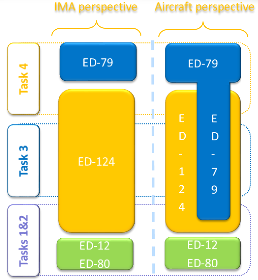 Figure 5 — Links between ED-124 tasks and other guidelines 3.1.3.3. Tailoring of ED-124 tasks A task framework is proposed by ED-124, but it is not the purpose of AMC 20-170 to enforce this division of tasks. The allocation of the ED-124 objectives to the ED-124 tasks can be tailored by the applicant. For instance, an IMA specificity is the need to coordinate verification activities such that the performance of the integrated IMA system can be guaranteed without requiring the reverification of each hosted application on the entire integrated system: — ED-124 Chapter 3.1.3 d.2 may be interpreted as requesting that IMA integration should be performed with the full set of applications. However, the applicant may integrate and verify applications independently on the IMA platform, taking into account the platform properties (e.g. robust partitioning and resource management). — Some Task 3 objectives may be already anticipated and accomplished during Task 2, or they may be deferred to Task 4. If the applicant intends to develop an IMA system and the supported aircraft functions by tailoring the ED-124 tasks or by following another framework, the applicant should detail the division of tasks, the objectives of each work package, and the associated activities. The applicant should describe how the work package objectives are mapped to the ED-124 objectives in order to ensure that the objectives of ED-124 are met within the alternative framework presented by the applicant. The ED-124 life cycle data can be also adapted to the division of tasks and work packages defined by the applicant. Moreover, ED-124 Task 4 may have few IMA specificities compared to a federated architecture. The achievement of Task 4 to support compliance demonstration in the frame of this AMC could be deemed to be outside the scope of this AMC, provided that: — the aircraft integration activity is covered through other guidance and its related applicant processes (to be clarified in the certification plan); — Task 3 is complete: meaning that no objectives, activities, or life cycle data are deferred to or covered by Task 4. Another area where tailoring can be performed is requirement validation. ED-124 Chapter 5.3.a. considers that each level of requirements within the hierarchy should be validated prior to validating the next lower level. A strict interpretation of this statement would not allow the development of a platform based on the assumptions for the intended use without consideration of the final aircraft functions (as suggested in Chapter 4.2.1.b). Also, it would imply a top-down approach from the aircraft functions to the level of hardware and the core/support software, which may not be relevant. A bottom-up approach is also feasible, which involves ensuring that the platform usage rules and constraints identified in the platform user guide/manual (Chapter 4.2.12.e.) are fulfilled, and that they satisfy the IMA system requirements. 3.1.4. Use of alternative means to demonstrate compliance If an applicant elects to comply with an alternative means to demonstrate compliance with the CS, consistency with the ED-124 acceptance objectives in Annex A tables [A1-A6] (IMA module/platform development process objectives) should be demonstrated. Early coordination with EASA should be ensured. 3.2. Use of previously recognised means of compliance Applicants who did not use this AMC in their past IMA certifications and who successfully used other means of compliance that were: — discussed in specific CRI(s); — previously recognised as equivalent to the ED-124 objectives; and — previously accepted by EASA for covering IMA certification concerns, may use the same means of compliance for their certification project, provided that the IMA system is similar to the previously certified one (i.e. with a similar architecture, the same design concepts, the same development process, and the same certification approach). Early coordination with EASA to confirm the use of the applicant’s previously recognised means of compliance should be ensured. 3.3. Role of the IMA system certification plan ED-124 objectives can be met by using various industrial mappings, based on the sharing of roles, activities and life cycle data. The strategy selected for demonstration of compliance with this AMC should be defined by the applicant in their certification plans. An IMA system certification plan should introduce the planning, the organisation, the work share, work packages, and the development, validation, integration, and verification activities of the IMA system. Considerations regarding the content of an IMA system certification plan can be found in ED-124 Chapter 4.4.3. The certification plan should particularly emphasise the following topics: — The scope covered by the IMA system certification plan and its relationship with other certification plans, including the certification plans of the aircraft functions hosted (totally or partially) on the IMA system. — The strategy proposed by the applicant to demonstrate compliance with this AMC, including: — the certification approach selected (see paragraph 3); — the relationship and credit potentially taken from other standards or processes to satisfy the objectives of ED-124; — the nature and extent of credit claimed from previously approved components (i.e. having obtained an ETSOA) or from activities performed on components reused from previous certification projects (see paragraph 4); — the identification of modules, platforms and applications for which full or partial incremental compliance credit is sought. — The industrial organisation supporting the IMA system development and certification, including the roles, responsibilities and work share between the stakeholders, with, in particular: — the sharing of activities related to aircraft functions hosted on the IMA platform and the IMA system integration activities; — when applicable, the tailoring and scope of the ED-124 tasks, or ED-124 life cycle data; — the work package allocated to each IMA stakeholder, including the design, validation, verification and integration activities, including environmental qualification under their responsibility and the credit claimed for the incremental certification. — The activities planned for the integration of the IMA system and its installation on an aircraft with an emphasis on: — the establishment of full or partial incremental credit gained from the integration, validation and verification activities conducted at each stage of the development, with their associated transition criteria. If a future step cannot be planned by a stakeholder, who for instance would — only perform the development of a function, the interface to future steps and the assumptions made (e.g. on resources used) need to be identified; — the credit expected from the characteristics of the IMA platform to independently verify aircraft functions allocated or partially allocated to the IMA system; — the activities to be completed for the installation of an ETSO-2C153 or C214 article; — the rationale for not performing some ground or flight tests when the IMA system is installed on the aircraft. — A description of the development and verification environments, with emphasis on the tools used to generate data or automate the activities and the rationale for the qualification or non-qualification of the tools. Note: A dedicated IMA system certification plan may not be required provided that its role is equivalently performed by a comprehensive set of documents in the applicant’s data package. 4. Incremental certification process As indicated in Section 3.1.2, the concepts of ‘letters of acceptance’ and of ‘reusable software components (RSCs)’ are not compatible with the EASA system. Furthermore, within the EASA system, there is currently no means to benefit from the certification credit granted within a TC or an STC in the frame of another product certification. Formal compliance credit can only be claimed from an ETSOA. However, the lack of an ETSOA, or the absence of a letter of acceptance, does not prevent an applicant from incrementally building confidence and demonstrating compliance of IMA components during the development flow (as per the ED-124 task framework), nor does it prevent the reuse of previous certification artefacts and activities for a new demonstration of compliance. The incremental certification process is the process to certify a product for which EASA agrees to grant some credit to a component/module, application or system, before that module, application or system is configured, integrated and certified as part of the final product. The incremental certification process applies to the following approaches: (a) Incremental component qualification: credit is taken from activities performed during various steps of the development in order to reduce the effort during a subsequent phase (e.g. verification activities). This qualification is mainly built up using the incremental verification approach. (b) Reuse: credit is taken from activities performed on components (modules, platforms, applications) reused from other projects. This approach encompasses the components reused from a previously approved TC or from legacy IMA systems. (c) Compliance credit: formal credit is claimed from an ETSOA. In all cases, the applicant should evaluate and substantiate the suitability and level of the credit sought. Early coordination with EASA should be ensured. Note: An ETSOA is not a mandatory step in the certification of an IMA system. <table border="1" cellpadding="0" cellspacing="0" width="571"> <thead> <tr> <td colspan="2" width="129"> <p align="center"><b>Approach</b></p> </td> <td width="133"> <p align="center"><b>Demonstration of compliance — responsibilities</b></p> </td> <td width="150"> <p align="center"><b>Applicant activities</b></p> </td> <td width="159"> <p align="center"><b>Evidence supporting the claim</b></p> </td> </tr> </thead> <tr> <td valign="top" width="32"> <p>(a)</p> </td> <td valign="top" width="97"> <p>Incremental component qualification</p> <p>See paragraph 4.1</p> </td> <td valign="top" width="133"> <p>Under the full responsibility of the applicant*.</p> </td> <td valign="top" width="150"> <p>Full compliance demonstration is expected from the applicant.</p> </td> <td valign="top" width="159"> <p>Evidence of review and acceptance by the applicant, covering all objectives for which credit is sought, including final review reports (at software, hardware, platform, IMA system level(s), as applicable).</p> </td> </tr> <tr> <td valign="top" width="32"> <p>(b)</p> </td> <td valign="top" width="97"> <p>Reuse from previous TC</p> <p>See paragraph 4.2</p> </td> <td valign="top" width="133"> <p>Under the full responsibility of the applicant*.</p> </td> <td valign="top" width="150"> <p>Compliance demonstration may be tailored depending on the agreement with EASA**.</p> <p>Note: Demonstration of compliance for the IMA components may be reduced (e.g. no software development and verification reviews (SOI#2&3) as part of Task 2).</p> </td> <td valign="top" width="159"> <p>Previous set of evidence.</p> <p>Evidence of review and acceptance by the applicant, covering all objectives for which credit is sought, including final review reports (at software, hardware, platform, IMA system level(s), as applicable).</p> </td> </tr> <tr> <td valign="top" width="32"> <p>(c)</p> </td> <td valign="top" width="97"> <p>Compliance credit</p> <p>See paragraph 4.3</p> </td> <td valign="top" width="133"> <p>Shared between the:</p> <p>ETSO holder for the scope covered by the ETSOA (e.g. module/platform);</p> <p>applicant* for the completion of integration and/or installation activities. </p> </td> <td valign="top" width="150"> <p>Compliance demonstration is reduced according to the certification credit claimed from the ETSOA.</p> </td> <td valign="top" width="159"> <p>ETSOA</p> </td> </tr> </table> Incremental certification evidence table \* Applicant stands for the applicant developing and/or installing the IMA system. \*\* Discussions held on a case-by-case basis based on the information provided through the certification plan. Whatever the approach selected for the recognition of credit and the level of credit granted, the applicant remains responsible for ensuring and for demonstrating that each component is integrated and installed consistently with its function, interfaces, usage domain, and limitations. 4.1. Incremental component qualification One main characteristic of IMA systems and the ED-124 task framework is that they allow a high level of independence in the design and verification activities: — between the functional level (application) and the resource level (module/platform); — between different applications (except for possible functional coupling between applications). In addition, Chapter 2.2.e of ED-124 introduces the concept of ‘composability’, where the integration of a new application does not invalidate any of the verified requirements of an already integrated application. When an IMA system is ‘composable’, credit can be taken from its properties (e.g. robust partitioning) regarding two aspects: — during the development of the application itself: credit may be taken from module/platform development activities; — during the integration and verification activities: credit may be taken from the integration of the application and from the absence of impact on other already verified and installed applications. These principles drive a modular approach, which can be used to support an incremental component qualification process, provided the following considerations are fulfilled: — The applicant should define criteria and supporting evidence to demonstrate the achievement of all objectives for which credit is sought. — The applicant should assess, and record through a formal review, the achievement and acceptance of a set of objectives for a given component. For instance, a final software and hardware review (SOI#4) on the components of a module and the acceptance of the corresponding software and hardware accomplishment summaries could support the completion of ED-124 Task 1. Depending on the framework and organisation, strict AMC 20-115() or ED-80 compliance may not, on its own, be sufficient to show the achievement of a given task. Complementary accomplishment summaries should be provided and encompassed in the applicant’s review. 4.2. Reuse of components The applicant remains fully responsible for the contents of the associated data, which have to be assessed through the applicant’s activities as being reusable in the context of the current certification project. 4.2.1. Reuse from a legacy IMA system Components that were previously approved may be reused provided that the applicant shows that the reuse of the component is appropriate. If changes are necessary, a change impact analysis should be performed to identify the scope of the changes and the necessary activities to re-engage in to cover the changes. 4.2.2. Reuse from a previous ED-124 project The management of reused components is addressed through ED-124 Task 6 (ED-124 Chapter 4.7). If changes are intended, they should be managed through ED-124 Task 5 (ED-124 Chapter 4.6). Note: To facilitate the reuse of a component, ED-124 recommends developers to anticipate such reuse during the initial development through dedicated objectives that are part of Tasks 1 & 2 (e.g. the module acceptance plan providing the data listed in Chapter 4.2.3.h). 4.3. Compliance credit In the frame of this AMC, formal certification credit is offered from an ETSOA granted to: — platform(s)/module(s): ETSO-2C153; — application(s) integrated with an ETSO-2C153 module/platform: ETSO-C214. 4.3.1. Use of an ETSO-2C153 authorisation An ETSO-2C153 can be granted to a platform(s)/module(s) in order to facilitate its (their) use in an IMA system. As per ETSO-2C153 paragraph 3.2.2.1, the IMA module or platform should meet the ED-124 Task 1 objectives. Compliance credit could be hence claimed by an applicant for the demonstration of compliance with ED-124 Task 1, provided the platform(s)/module(s) had obtained an ETSO-2C153 authorisation beforehand. Nevertheless, the ETSOA does not by itself ensure that the platform(s)/module(s) is (are) technically adequate to be integrated into the IMA system. The applicant remains responsible for all the activities to ensure the proper integration of the ETSO-2C153 platform(s)/module(s) into the IMA system, and the applicant should: — substantiate the scope of the ETSOA compliance credit, and define the complementary certification activities based on the data provided (e.g. user/installation manuals); — demonstrate the correct use of the platform(s)/module(s), including compliance: — with the platform/module integration requirements/user requirements, and the IMA system and safety requirements; — of the use, the partitioning, the health monitoring, the configuration of the resources and the installation of the items with the platforms/modules user guide/manual, installation manual, or equivalent data (as documented per ETSO-2C153 Appendix 3). This also includes the deactivation or disabling of unused ETSO-2C153 functions/modules, when available, or the means to ensure that the intended function is performed without any interference from unused ETSO-2C153 functions/ modules. This section only addresses the use of EASA ETSO-2C153, and its use cannot be extended to any other authority TSO standards on IMA platforms and modules that are not equivalent in their technical requirements. 4.3.2. Use of a functional ETSO-C214 authorisation Through a functional ETSO-C214 (F-ETSO), an authorisation can be granted to application(s) integrated with an ETSO-2C153 module/platform. As per ETSO-C214, compliance with the ED-124 Task 2 & 3 objectives has to be demonstrated. Compliance credit could hence be claimed by an applicant for the demonstration of compliance with ED-124 Tasks 2 & 3, provided that the F-ETSO-C214 authorisation had been obtained beforehand. Nevertheless, the functional ETSOA does not by itself ensure that the ETSO article is technically adequate to be installed in the product. The applicant remains responsible for all the activities to ensure the proper integration of the application(s)/module(s)/platform(s) into the IMA system, and the applicant should: — substantiate the scope of the ETSOA compliance credit, and define the complementary certification activities; — complete the demonstration that the function covered by the F-ETSO article complies with the IMA system and safety requirements. If the F-ETSO article is in the ‘open’ class and the applicant intends to perform incremental development on the ETSOA article (e.g. to add an application), the considerations of this AMC apply to the new and affected items. The applicant should ensure the integrity and continuity of the system configuration, and in particular should show that the resource allocation, partitioning, and health monitoring are not impaired by the intended changes to the ETSOA article. The level of credit that can be obtained from the F-ETSO article, and the certification activities to be completed in the frame of this AMC, will hence vary depending on the scope of the changes made to the initial F-ETSO article. If the F-ETSO article is in the ‘closed’ class, it no longer offers any capability for IMA development. Credit can be taken for ED-124 Tasks 2 and 3. This closed F-ETSO article is equivalent to a conventional ETSO article. 4.3.3. Summary of ETSO compliance credit The following table summarises the credit that can be claimed from ETSO-2C153 and ETSO-C214, and the remaining certification activities to support the demonstration of compliance with AMC 20-170: <table border="1" cellpadding="0" cellspacing="0" width="495"> <tr> <td valign="top" width="180"> <p align="center"><b>ETSOA</b></p> </td> <td valign="top" width="144"> <p align="center"><b>Credit</b></p> </td> <td valign="top" width="170"> <p align="center"><b>Remaining activities</b></p> </td> </tr> <tr> <td valign="top" width="180"> <p align="center">ETSO-2C153</p> <p><figure><img alt='Aviation.Bot AI suggestion, not from EASA source: **Overall Summary:** The image is a block diagram illustrating the relationship between multiple applications, a configuration table, and an ETSO-2C153 module or platform. **Detailed Description:** The diagram consists of four primary rectangular elements with rounded corners, arranged in two horizontal layers, connected by two bidirectional arrows. The top layer contains three vertically oriented, rounded rectangular blocks, aligned horizontally. * The leftmost block has a white fill with an orange border. It contains the text "Application 1" rotated 90 degrees clockwise, displayed in orange font. * The middle block has a white fill with a purple border. It contains the text "Application n" rotated 90 degrees clockwise, displayed in purple font. * The rightmost block has a white fill with a blue border. It contains the text "Configuration table" rotated 90 degrees clockwise, displayed in blue font. The bottom layer contains a single horizontally oriented, rounded rectangular block, centered beneath the top three blocks. * This block has a light green fill with a darker green border. It contains the text "ETSO-2C153" displayed in white font. Connecting the top and bottom layers are two light blue, double-headed arrows. * One arrow is positioned vertically between the "Application 1" block (top-left) and the "ETSO-2C153" block (bottom-center), indicating a bidirectional connection. * The second arrow is positioned vertically between the "Application n" block (top-middle) and the "ETSO-2C153" block (bottom-center), also indicating a bidirectional connection. * There is no direct arrow connection depicted between the "Configuration table" block and the "ETSO-2C153" block. The background of the image is solid black. **Contextual Linkage:** The diagram visually represents that "Application 1" and "Application n" (representing multiple applications) have a direct, bidirectional interaction or dependency with the "ETSO-2C153" component. The "Configuration table" is shown as a distinct but related element at the same level as the applications, suggesting it is part of the higher-level system that interacts with the ETSO-2C153.' src="/static/files/file_tNNDI2wQkpg/image086.png"/></figure></p> </td> <td valign="top" width="144"> <p align="center">Acceptance of the platform/module</p> <p align="center">(ED-124 Task 1)</p> </td> <td valign="top" width="170"> <p>Substantiation of the scope of ETSOA compliance credit.</p> <p>All subsequent activities (ED-124 Tasks 2 and 3, plus those deferred to Task 4).</p> </td> </tr> <tr> <td valign="top" width="180"> <p align="center">ETSO-C214 ‘open’ class</p> <p align="center"><figure><img alt='Aviation.Bot AI suggestion, not from EASA source: This image is a block diagram illustrating the hierarchical relationship and interaction between various applications, a configuration table, and two European Technical Standard Order (ETSO) authorizations, specifically ETSO-2C153 and ETSO-C214, within an integrated modular avionics (IMA) context. Detailed Description: The diagram is composed of several rounded rectangular blocks arranged vertically on a black background, with connections indicating relationships. At the top, there are three vertically oriented, rounded rectangular blocks, all of the same height and width, arranged horizontally. 1. The leftmost block is colored yellow and contains the white text "Application 1" rotated 90 degrees clockwise. 2. The middle block is white and contains the purple text "Application n" rotated 90 degrees clockwise. 3. The rightmost block is white and contains the blue text "Configuration table" rotated 90 degrees clockwise. Below these three blocks, and centrally aligned, is a single horizontally oriented, rounded rectangular block. This block is colored green and contains the white text "ETSO-2C153". Below the "ETSO-2C153" block, and centrally aligned, is another single horizontally oriented, rounded rectangular block. This block is also colored green and contains the white text "ETSO-C214". Two light blue, double-headed arrows indicate bidirectional communication or interaction. * One arrow extends vertically from the bottom center of the "Application 1" block to the top center of the "ETSO-2C153" block. * The second arrow extends vertically from the bottom center of the "Application n" block to the top center of the "ETSO-2C153" block. There are no explicit arrows connecting the "Configuration table" to "ETSO-2C153", nor are there any arrows connecting "ETSO-2C153" to "ETSO-C214". A dashed green line forms a large rounded rectangular boundary that encloses the three top blocks ("Application 1", "Application n", "Configuration table") and the "ETSO-2C153" block. This dashed line indicates a conceptual grouping or system boundary for these elements. The "ETSO-C214" block is positioned outside and below this dashed green boundary. Contextual Linkage: The diagram visually represents how "Application 1" and "Application n" interact with an "ETSO-2C153" module or platform, as indicated by the bidirectional arrows. The "Configuration table" is shown as a peer to the applications, also conceptually contained within the same system boundary as "ETSO-2C153". The "ETSO-C214" block is depicted as a foundational or underlying element, separate from but supporting the system defined by the dashed green line, implying a relationship where "ETSO-C214" might authorize or enable the components within the dashed boundary, particularly those related to "ETSO-2C153" and its hosted applications.' src="/static/files/file_tNNDI2wQkpg/image087.png"/></figure></p> </td> <td valign="top" width="144"> <p align="center">Acceptance of the platform/module</p> <p align="center">(ED-124 Task 1)</p> <p align="center">Acceptance of the non-impacted hosted application(s)</p> <p align="center">(ED-124 Task 2)</p> </td> <td valign="top" width="170"> <p>Substantiation of the scope of ETSOA compliance credit.</p> <p>Demonstration that the F-ETSO article complies with the IMA system and safety requirements.</p> <p>All activities impacted by the incremental development, such as on the modified or new hosted application (ED-124 Tasks 2), and IMA configuration and integration (ED-124 Task 3 plus those deferred to Task 4.)</p> </td> </tr> <tr> <td valign="top" width="180"> <p align="center">ETSO-C214 ‘closed’ class</p> <p align="center"><figure><img alt='Aviation.Bot AI suggestion, not from EASA source: The image is a conceptual diagram illustrating the hierarchical relationship and interaction between various applications, a configuration table, and two European Technical Standard Order (ETSO) standards, ETSO-2C153 and ETSO-C214, within an Integrated Modular Avionics (IMA) context. Detailed Description: The diagram consists of several rounded-rectangle blocks arranged vertically, with some horizontal alignment and connecting arrows. 1. **Top Layer:** Three vertically oriented, rounded-rectangle blocks are horizontally aligned at their top edges. * The leftmost block is yellow and contains the white text "Application 1", rotated 90 degrees clockwise. * The middle block is purple and contains the white text "Application n", rotated 90 degrees clockwise. * The rightmost block is blue and contains the white text "Configuration table", rotated 90 degrees clockwise. 2. **Middle Layer:** Below the top layer, there is a single horizontally oriented, rounded-rectangle block. * This block is light green and contains the white text "ETSO-2C153". 3. **Bottom Layer:** Below the middle layer, there is another single horizontally oriented, rounded-rectangle block. * This block is light green and contains the white text "ETSO-C214". 4. **Connecting Elements:** * Two light blue, double-headed arrows are positioned between the top and middle layers. * One arrow connects the bottom edge of the "Application 1" block to the top edge of the "ETSO-2C153" block. * The second arrow connects the bottom edge of the "Application n" block to the top edge of the "ETSO-2C153" block. * There is no explicit arrow connecting the "Configuration table" block to the "ETSO-2C153" block. 5. **Enclosing Boundary:** A thick, light green, rounded-corner outline encloses the "Application 1", "Application n", and "Configuration table" blocks, the two double-headed arrows, and the "ETSO-2C153" block. This outline visually groups these elements together, indicating they form a cohesive unit or system. The "ETSO-C214" block is positioned below and outside this green outline. Contextual Linkage: The diagram illustrates that "Application 1", "Application n", and a "Configuration table" are components that interact with or are hosted on an "ETSO-2C153" platform or module, as indicated by the bidirectional arrows from the applications to ETSO-2C153. The entire system comprising these applications, the configuration table, and the ETSO-2C153 platform is conceptually contained within or supported by "ETSO-C214", which is positioned as a foundational element below the green-outlined group. The green outline suggests that the applications, configuration table, and ETSO-2C153 collectively represent a functional unit or scope that is authorized or defined by ETSO-C214.' src="/static/files/file_tNNDI2wQkpg/image088.png"/></figure></p> </td> <td valign="top" width="144"> <p align="center">Acceptance of the platform/module</p> <p align="center">(ED-124 Task 1)</p> <p align="center">Acceptance of the hosted application(s)</p> <p align="center">(ED-124 Task 2)</p> <p align="center">IMA configuration and integration</p> <p align="center">(ED-124 Task 3)</p> </td> <td valign="top" width="170"> <p>Substantiation of the scope of ETSOA compliance credit.</p> </td> </tr> </table> ETSO compliance credit table for AMC 20-170 5. Additional recommendations for IMA system certification 5.1. Fault management and human factors ED-124 Chapter 3.6.5 deals with the annunciation of failures to the crew. CS XX.1322 and the associated AMC address flight crew alerting systems and warning, caution, or advisory lights. In any case where an inconsistency is identified between the text in ED-124 and the text in CS XX.1322 and the associated AMC, the text in CS XX.1322 and the associated AMC should prevail. Similarly, for any inconsistency between the text in ED-124 Chapter 3.10 dealing with human factors and the text in CS XX.1302 and the associated AMC, the text in CS XX.1302 and the associated AMC should prevail. 5.2. Configuration data/parameter data items Guidance on IMA configuration data is provided in ED-124 Chapter 3.7.1.1 at the IMA system level and in Chapter 3.7.1.2 at the application level. These data items are nowadays described as ‘parameter data items’ as defined in ED-12C and should be treated in the same way as other elements of the software. Depending on how a parameter data item is to be used in the IMA system or application, it needs to be defined, managed and documented at the appropriate level (platform, module, application) and to comply with the AMC 20-115()[[50]](#_ftn50) guidance, including the process to ensure intermixability and compatibility during the post-TC period as indicated in ED-124. In particular, any parameter data item should be assigned the same software level as the component using it. 5.3. Use of tools and the need for qualification IMA system development may be supported by the use, at the system level, of tools in order to eliminate, reduce, or automate the activities associated with the ED-124 objectives. If a tool could introduce an error or could fail to detect an error, and there are no other alternative means to detect the issue, qualification of the tool is needed. For instance, a tool may be used to generate and/or verify IMA configuration data and may produce an erroneous configuration that is not necessarily easily detectable at a subsequent integration/verification step. The objectives of tool qualification are to: — ensure an equivalent level of confidence to the non-automated process/activities; — demonstrate that the tool complies, and its qualification is commensurate, with the intended use. Adequate guidance for tool qualification is provided in ED-215, Software Tool Qualification Considerations, and should be followed when a tool is intended to be qualified to support the IMA system development. The following criteria should be used to determine the appropriate tool qualification level (TQL), according to its intended use: (a) Impact of the tool: (1) Criterion 1: a tool whose output is part of the IMA system and thus could introduce an error. (2) Criterion 2: a tool that automates verification process(es) and thus could fail to detect an error, and whose output is used to justify the elimination or reduction of: — verification process(es) other than that (those) automated by the tool; or — development process(es) that could have an impact on the IMA system. (3) Criterion 3: a tool that, within the scope of its intended use, could fail to detect an error. (b) IDAL of the IMA component supported by the tool: <table border="1" cellpadding="0" cellspacing="0" width="493"> <thead> <tr> <td rowspan="2" width="123"> <p align="center"><b>IDAL</b></p> </td> <td colspan="3" width="370"> <p align="center"><b>Criteria</b></p> </td> </tr> <tr> <td width="123"> <p align="center"><b>1</b></p> </td> <td width="123"> <p align="center"><b>2</b></p> </td> <td width="123"> <p align="center"><b>3</b></p> </td> </tr> </thead> <tr> <td valign="top" width="123"> <p align="center">A</p> </td> <td valign="top" width="123"> <p align="center">TQL-1</p> </td> <td valign="top" width="123"> <p align="center">TQL-4</p> </td> <td valign="top" width="123"> <p align="center">TQL-5</p> </td> </tr> <tr> <td valign="top" width="123"> <p align="center">B</p> </td> <td valign="top" width="123"> <p align="center">TQL-2</p> </td> <td valign="top" width="123"> <p align="center">TQL-4</p> </td> <td valign="top" width="123"> <p align="center">TQL-5</p> </td> </tr> <tr> <td valign="top" width="123"> <p align="center">C</p> </td> <td valign="top" width="123"> <p align="center">TQL-3</p> </td> <td valign="top" width="123"> <p align="center">TQL-5</p> </td> <td valign="top" width="123"> <p align="center">TQL-5</p> </td> </tr> <tr> <td valign="top" width="123"> <p align="center">D</p> </td> <td valign="top" width="123"> <p align="center">TQL-4</p> </td> <td valign="top" width="123"> <p align="center">TQL-5</p> </td> <td valign="top" width="123"> <p align="center">TQL-5</p> </td> </tr> </table> 5.4. Change management This section deals not only with changes to components that were previously accepted through a TC, STC or ETSOA, but also with changes during the development as soon as components are delivered for use in a subsequent stage of the process and a formal baseline is established for these components. The main objectives of the change management process are to conduct and document a change impact analysis and to reintegrate the changed component into the IMA system, performing all the necessary verification, validation, and integration activities (including regression analysis and testing). (a) Since there are various levels of development and integration in an IMA system, and potentially various stakeholders (the module/platform developer, application developer, IMA system integrator, aircraft designer), agreements should be concluded between stakeholders to establish the way to communicate changes and to perform impact analyses at each level. (b) A change impact analysis should consider the possible impacts to be reported at each relevant level: — changes at the resource allocation level; — changes at the module/platform level; — changes at the application level. (c) Impacts on incremental compliance credit (if applicable) also need to be considered. (d) The changes should be documented in the appropriate life cycle data, including the trace data, configuration indexes and accomplishment summaries. 5.5. Management of problem reports IMA systems contain multiple applications hosted on the same IMA module/platform, therefore any OPR related to a module/platform or application, collected at any level, could affect one or several aircraft functions directly or indirectly. Considering the diversity of stakeholders in an IMA system, the management of problem reports can be more complex than with federated systems. In addition to the applicable guidance on OPR management, for IMA systems, the applicant should organise the management of OPRs, focusing on: — the evaluation of the potential effect of each OPR on any shared resources and IMA services, and the evaluation of those OPRs for impact on any aircraft function that uses the affected shared resources and IMA services; — the verification that necessary workarounds, including limitations, at the application and/or system levels, are documented within the IMA documentation (e.g. user guide/manual). In such cases, the efficiency of a workaround should be substantiated and the successful (i.e. complete and correct) deployment of the workaround should be ensured. NOTE: In order to facilitate the assessment and the communication between stakeholders, the use of a harmonised classification scale for OPRs is recommended. 5.6. Environmental qualification The scope of this section is to provide environmental qualification guidance complementary to ED-124 Chapter 5.2.6 for the environmental qualification of an IMA system. It can be an IMA platform composed of only one LRU, or various modules in a given configuration. The platform is qualified in conditions of the same severity as those expected when installed on the aircraft, interfaced with its peripherals through the aircraft (or equivalent) harnesses, and loaded with its set of applications. The acceptance criteria to qualify the platform are driven by the operational requirements of a given aircraft. Level of qualification testing activities: The modularity of an IMA platform makes it possible to conduct qualification testing activities at various stages: — IMA module testing: the testing is performed on an IMA module, involving the shared resources (hardware and/or software), and when relevant, with a representative set of software applications loaded onto the module. In the case of a cabinet, the module can be a chassis and/or a backplane. — IMA platform testing: the testing is performed on the platform or cabinet (chassis and backplane) equipped with its modules, and when relevant, loaded with a representative set of software applications. — System testing: the testing is performed on a set of modules and/or the backplane installed in the cabinet, with system peripherals interfaced with the cabinet, and with representative software applications loaded onto the modules. — Aircraft testing: the testing is performed with the systems installed on the aircraft. The modularity of the IMA platform, combined with the variety of its possible configurations, leads to the establishment of principles to reuse qualification credit for IMA modules in the context of qualifying a desired IMA platform for a given aircraft: (a) The environmental usage domain of an IMA module is the set of environmental conditions for which it is qualified. This is documented in the module user guide/manual. (b) For an IMA module integrated within a cabinet, its environmental qualification conditions should consider: — its environmental conditions (i.e. the envelope of thermal, electromagnetic, vibration, lightning, etc., conditions) encountered inside the cabinet when in use on the aircraft; — all its possible arrangements in the cabinet (i.e. different IMA platform configurations). Incremental environmental qualification is an approach used in qualifying a cabinet populated with modules in a known configuration for a given aircraft, relying on existing qualification credit for IMA modules in their environmental usage domain, and identifying any complementary qualification substantiation that would be necessary to cover the envelope of the environmental conditions of the aircraft. Thus it provides the latitude to populate a cabinet with already qualified modules, to qualify it without having to perform a full reassessment of the qualification of each module, and the capability to reuse its existing qualification dossier. All the substantiation data recorded in the qualification plan should be based on dedicated tests or on equivalence with the reuse of existing qualification results, or existing authorisations such as ETSO-2C153. The representativeness of the substantiation should consider the testing configuration, the testing conditions (including electrical, thermal, mechanical interfaces, etc.), the qualification testing level, the application software used for the testing, the test scenario and the level of stress applied. When an IMA system change is implemented, a change impact analysis should be conducted against the qualified configuration to assess the complementary qualification substantiation to be provided for each of its modules. [Amdt 20/15] --- [[50]](#_ftnref50) Starting from AMC 20-115D.
AMC 20-170 Integrated modular avionics (IMA) ED Decision 2018/008/R 1. Introduction 1.1. Purpose This Acceptable Means of Compliance (AMC) provides a means that can be used to demonstrate that the safety aspects of integrated modular avionics (IMA) systems comply with the airworthiness requirements when such systems are integrated in a product, a part, or an appliance submitted to EASA for approval. Compliance with this AMC is not mandatory and hence an applicant may elect to use alternative means of compliance. However, those alternative means of compliance must meet the relevant certification specifications, ensure an equivalent level of safety, and be accepted by EASA on a product basis. 1.2. Scope and applicability The guidance contained in this AMC applies to any type certificate (TC) or supplemental type certificate (STC) applicants seeking approval from EASA for IMA systems installed in aircraft or rotorcraft. IMA is a shared set of flexible, reusable and interoperable hardware and software resources that, when integrated, form a system that provides computing resources and services to hosted applications performing aircraft functions [ED-124]. An IMA architecture may integrate several aircraft functions on the same platform. Those functions are provided by several hosted applications that have historically been contained in functionally and physically separated ‘boxes’ or line replaceable units (LRUs). This AMC addresses certification considerations for IMA systems, and should apply when: — hosted applications\* on the same platform are designed, verified and integrated independently (at application level\*\*) from each other; and — the platforms/modules provide shared resources (typically designed, verified and integrated independently from the hosted applications), OR — a process for obtaining incremental certification\*\*\* credit is anticipated or applied. \* A single application hosted on an independently developed platform is considered to be a traditional federated architecture and thus is not subject to this AMC. However, if additional application(s) that is (are) independently developed is (are) hosted on the same platform at a later stage (e.g. through a major change), this AMC should be applied. \*\* Software integration/verification activities are not performed on the whole set of integrated software as in a federated architecture. \*\*\* Credit for incremental certification in an IMA context as detailed in Section 4. An applicant may choose to apply this AMC for a system which would not fulfil the conditions above. In that case, early discussions should take place between the applicant and EASA in order to confirm whether this AMC should be followed or not. 1.3. Document overview This document: (a) provides an overview of and background information on IMA systems and on concerns related to their certification (Section 2); (b) presents the EASA policy for IMA certification by recognising the use of EUROCAE document ED-124, Integrated Modular Avionics (IMA) Development Guidance and Certification Considerations, as an acceptable means of compliance for the development and certification of IMA systems. It also clarifies and amends the intent, scope, and use of that document (in Section 3); (c) introduces the incremental certification approach, and introduces the link to ETSO authorisations (ETSOAs) (in Section 4); (d) complements ED-124 with additional considerations on dedicated topics, such as environmental qualification, open problem reports (OPRs), and configuration files (in Section 5). 1.4. Documents to be used with this AMC This AMC should be used together with the following documents. The applicable version of the documents for a given project will be established in the certification basis or in the applicable CRIs. <table border="1" cellpadding="0" cellspacing="0" width="532"><tr><td valign="top" width="129"><p><b>Reference</b></p></td><td valign="top" width="403"><p align="center"><b>Title</b></p></td></tr><tr><td valign="top" width="129"><p>ED-124/DO-297</p></td><td valign="top" width="403"><p>Integrated Modular Avionics (IMA) Development Guidance and Certification Considerations</p></td></tr><tr><td valign="top" width="129"><p>ED-79/ARP4754*</p></td><td valign="top" width="403"><p>Certification Considerations for Highly-Integrated or Complex Aircraft Systems</p></td></tr><tr><td valign="top" width="129"><p>ED-79A/ARP4754A</p></td><td valign="top" width="403"><p>Guidelines for Development of Civil Aircraft and Systems</p></td></tr><tr><td valign="top" width="129"><p>ED-12()/DO-178()**</p></td><td valign="top" width="403"><p>Software Considerations in Airborne Systems and Equipment Certification</p></td></tr><tr><td valign="top" width="129"><p>ED-80/DO-254</p></td><td valign="top" width="403"><p>Design Assurance Guidance for Airborne Electronic Hardware</p></td></tr><tr><td valign="top" width="129"><p>ARP4761()</p></td><td valign="top" width="403"><p>Guidelines and Methods for Conducting the Safety Assessment Process on Airborne Systems and Equipment</p></td></tr><tr><td valign="top" width="129"><p>ED-14()/DO-160()</p></td><td valign="top" width="403"><p>Environmental Conditions And Test Procedures For Airborne Equipment</p></td></tr><tr><td valign="top" width="129"><p>ED-215/DO-330</p></td><td valign="top" width="403"><p>Software Tool Qualification Considerations</p></td></tr></table> \* ED-79A should be used, unless ED-79 is the applicable document in a given project. \*\* Recommendations for software are developed in AMC 20-115(). 1.5. Referenced material 1.5.1. Certification specifications (CS) and acceptable means of compliance (AMC) <table border="1" cellpadding="0" cellspacing="0" width="491"><thead><tr><td valign="top" width="100"><p><b>Reference</b></p></td><td valign="top" width="391"><p align="center"><b>Title</b></p></td></tr></thead><tr><td valign="top" width="100"><p>CS XX.1301</p></td><td valign="top" width="391"><p>Function and installation</p></td></tr><tr><td valign="top" width="100"><p>CS XX.1302</p></td><td valign="top" width="391"><p>Installed systems and equipment for use by the flight crew</p></td></tr><tr><td valign="top" width="100"><p>CS XX.1309</p></td><td valign="top" width="391"><p>Equipment, systems and installations</p></td></tr><tr><td valign="top" width="100"><p>AC 23.1309-1()</p></td><td valign="top" width="391"><p>System safety analysis and assessment for Part 23 airplanes</p></td></tr><tr><td valign="top" width="100"><p>AMC 25.1309</p></td><td valign="top" width="391"><p>System design and analysis</p></td></tr><tr><td valign="top" width="100"><p>AC 27.1309</p></td><td valign="top" width="391"><p>Equipment, systems and installations</p></td></tr><tr><td valign="top" width="100"><p>AC 29.1309</p></td><td valign="top" width="391"><p>Equipment, systems and installations</p></td></tr><tr><td valign="top" width="100"><p>CS XX.1322</p></td><td valign="top" width="391"><p>Flight crew alerting</p></td></tr><tr><td valign="top" width="100"><p>CS-E 50</p></td><td valign="top" width="391"><p>Engine control system</p></td></tr><tr><td valign="top" width="100"><p>AMC E 50</p></td><td valign="top" width="391"><p>Engine control system</p></td></tr><tr><td valign="top" width="100"><p>AMC 20-3</p></td><td valign="top" width="391"><p>Certification of engines equipped with electronic engine control systems</p></td></tr><tr><td valign="top" width="100"><p>AMC 20-115()</p></td><td valign="top" width="391"><p>Software considerations for certification of airborne systems and equipment</p></td></tr><tr><td valign="top" width="100"><p>ETSO-2C153</p></td><td valign="top" width="391"><p>Integrated Modular Avionics (IMA) platform and modules</p></td></tr><tr><td valign="top" width="100"><p>ETSO-C214</p></td><td valign="top" width="391"><p>Functional-ETSO equipment using authorised ETSO-2C153 IMA platform or module</p></td></tr></table> The applicable version of the documents for a given project will be established in the certification basis or in the applicable CRIs. 1.5.2. Referenced documents <table border="1" cellpadding="0" cellspacing="0" width="491"><tr><td valign="top" width="100"><p><b>Reference</b></p></td><td valign="top" width="391"><p align="center"><b>Title</b></p></td></tr><tr><td valign="top" width="100"><p>ED-94C</p></td><td valign="top" width="391"><p>Supporting information for ED-12C and ED-109A</p></td></tr></table> 1.6. Definitions and abbreviations 1.6.1. Definitions <table border="1" cellpadding="0" cellspacing="0" width="493"><thead><tr><td valign="top" width="99"><p><b>Term</b></p></td><td valign="top" width="394"><p align="center"><b>Meaning</b></p></td></tr></thead><tr><td valign="top" width="99"><p>Aircraft function</p></td><td valign="top" width="394"><p>A capability of the aircraft that is provided by the hardware and software of the systems on the aircraft. [ED-124]</p></td></tr><tr><td valign="top" width="99"><p>Application</p></td><td valign="top" width="394"><p>Software and/or application-specific hardware with a defined set of interfaces that, when integrated with a platform(s), performs a function. [ED-124]</p></td></tr><tr><td valign="top" width="99"><p>Cabinet</p></td><td valign="top" width="394"><p>Result of the integration of hardware modules mounted within one rack. [ETSO‑2C153]</p></td></tr><tr><td valign="top" width="99"><p>Compliance credit</p></td><td valign="top" width="394"><p>Evidence that a set of objectives related to certification requirements has been reached for a component or a set of components.</p><p>Credit can be full or partial, meaning that, in case of partial credit, some objectives allocated to the component were not yet satisfied and should be completed at another stage.</p></td></tr><tr><td valign="top" width="99"><p>Component</p></td><td valign="top" width="394"><p>A self-contained hardware part, software part, database, or combination of them that is configuration-controlled. A component does not provide an aircraft function by itself. [ED-124 Chapter 2.1.1]</p></td></tr><tr><td valign="top" width="99"><p>Core software</p></td><td valign="top" width="394"><p>The operating system and support software that manage resources to provide an environment in which applications can execute. Core software is a necessary component of a platform and is typically comprised of one or more modules (such as, for example, libraries, drivers, kernel, data-loading, boot, etc.). [ED-124]</p></td></tr><tr><td valign="top" width="99"><p>Federated system</p></td><td valign="top" width="394"><p>Aircraft equipment architecture consisting of primarily line replaceable units that perform a specific function, connected by dedicated interfaces or aircraft system data buses. [ED-124]</p></td></tr><tr><td valign="top" width="99"><p>IMA system</p></td><td valign="top" width="394"><p>Consists of an IMA platform(s) and a defined set of hosted applications. [ETSO‑2C153]</p></td></tr><tr><td valign="top" width="99"><p>Incremental certification</p></td><td valign="top" width="394"><p>The incremental certification process is the process by which EASA agrees to grant compliance credit to IMA modules/platforms or hosted applications considered independently, based on activities performed at intermediate steps.</p></td></tr><tr><td valign="top" width="99"><p>Intermixability</p></td><td valign="top" width="394"><p>The capability to intermix software and/or hardware of different versions and/or modification standards. [ED-124]</p></td></tr><tr><td valign="top" width="99"><p>Interoperability</p></td><td valign="top" width="394"><p>The capability of several modules to operate together to accomplish a specific goal or function. [ED-124]</p></td></tr><tr><td valign="top" width="99"><p>Module</p></td><td valign="top" width="394"><p>A component or collection of components that may be accepted by themselves or in the context of an IMA system. A module may also comprise other modules. A module may be software, hardware, or a combination of hardware and software, which provides resources to the IMA system hosted applications. [ED-124]</p></td></tr><tr><td valign="top" width="99"><p>Module/ platform configuration</p></td><td valign="top" width="394"><p>The action of setting some adjustable characteristics of the module/platform in order to adapt it to the user context.</p><p>By extension, the result of this action.</p><p>NOTE: A configuration table is one way but not the only way to configure a module/ platform.</p></td></tr><tr><td valign="top" width="99"><p>Partitioning and robust partitioning</p></td><td valign="top" width="394"><p>Partitioning is ‘An architectural technique to provide the necessary separation and independence of functions or applications to ensure that only intended coupling occurs.’ [ED-124]</p><p>Robust partitioning is a means for assuring the intended isolation in all circumstances (including hardware failures, hardware and software design errors, or anomalous behaviour) of aircraft functions and hosted applications using shared resources. The objective of robust partitioning is to provide a level of functional isolation and independence equivalent to that of a federated system implementation.</p></td></tr><tr><td valign="top" width="99"><p>Platform</p></td><td valign="top" width="394"><p>A module or group of modules, including core software, that manages resources in a manner sufficient to support at least one application. [ED-124]</p></td></tr><tr><td valign="top" width="99"><p>Resource</p></td><td valign="top" width="394"><p>Any object (processor, memory, software, data, etc.) or component used by a processor, IMA platform, core software or application. A resource may be shared by multiple applications or dedicated to a specific application. A resource may be physical (a hardware device) or logical (a piece of information). [ED-124]</p></td></tr><tr><td valign="top" width="99"><p>Support software</p></td><td valign="top" width="394"><p>Embedded software necessary as a complement to the operating system to provide general services such as contributing to the intended function of resources sharing, handling hardware, drivers, software loading, health monitoring, boot strap, etc. [ETSO-2C153]</p></td></tr><tr><td valign="top" width="99"><p>Usage domain</p></td><td valign="top" width="394"><p>The usage domain of an IMA module is defined as an exhaustive list of conditions (such as configuration settings, usage rules, etc.) to be respected by the user(s) to ensure that the IMA module continues to meet its characteristics. Compliance with the usage domain ensures that:</p><p>the module is compliant with its functional, performance, safety and environmental requirements specified for all implemented intended functions;</p><p>the module characteristics documented in the user guide/manual remain at the levels guaranteed by the manufacturer;</p><p>the module remains compliant with the applicable airworthiness requirements (including continuing airworthiness aspects).</p><p>[Adapted from ETSO-2C153, without reference to the ETSO Minimum Performance Standard]</p></td></tr></table> 1.6.2. Abbreviations <table border="1" cellpadding="0" cellspacing="0" width="492"><thead><tr><td valign="top" width="98"><p><b>Abbreviation</b></p></td><td valign="top" width="394"><p align="center"><b>Meaning</b></p></td></tr></thead><tr><td valign="top" width="98"><p>AEH</p></td><td valign="top" width="394"><p>airborne electronic hardware</p></td></tr><tr><td valign="top" width="98"><p>AMC</p></td><td valign="top" width="394"><p>acceptable means of compliance</p></td></tr><tr><td valign="top" width="98"><p>API</p></td><td valign="top" width="394"><p>application programming interface</p></td></tr><tr><td valign="top" width="98"><p>ATA</p></td><td valign="top" width="394"><p>air transport association of America</p></td></tr><tr><td valign="top" width="98"><p>CRI</p></td><td valign="top" width="394"><p>certification review item</p></td></tr><tr><td valign="top" width="98"><p>CS</p></td><td valign="top" width="394"><p>certification specification</p></td></tr><tr><td valign="top" width="98"><p>EASA</p></td><td valign="top" width="394"><p>European Aviation Safety Agency </p></td></tr><tr><td valign="top" width="98"><p>ETSO</p></td><td valign="top" width="394"><p>European technical standard order</p></td></tr><tr><td valign="top" width="98"><p>ETSOA</p></td><td valign="top" width="394"><p>European technical standard order authorisation</p></td></tr><tr><td valign="top" width="98"><p>F-ETSO</p></td><td valign="top" width="394"><p>functional ETSO</p></td></tr><tr><td valign="top" width="98"><p>HW</p></td><td valign="top" width="394"><p>hardware</p></td></tr><tr><td valign="top" width="98"><p>IDAL</p></td><td valign="top" width="394"><p>item development assurance level</p></td></tr><tr><td valign="top" width="98"><p>I/O</p></td><td valign="top" width="394"><p>input/output</p></td></tr><tr><td valign="top" width="98"><p>IMA</p></td><td valign="top" width="394"><p>integrated modular avionics</p></td></tr><tr><td valign="top" width="98"><p>LRU</p></td><td valign="top" width="394"><p>line replaceable unit</p></td></tr><tr><td valign="top" width="98"><p>MMEL</p></td><td valign="top" width="394"><p>master minimum equipment list</p></td></tr><tr><td valign="top" width="98"><p>OPR</p></td><td valign="top" width="394"><p>open problem report</p></td></tr><tr><td valign="top" width="98"><p>RSC</p></td><td valign="top" width="394"><p>reusable software component</p></td></tr><tr><td valign="top" width="98"><p>SOI</p></td><td valign="top" width="394"><p>stage of involvement</p></td></tr><tr><td valign="top" width="98"><p>STC</p></td><td valign="top" width="394"><p>supplemental type certificate</p></td></tr><tr><td valign="top" width="98"><p>SW</p></td><td valign="top" width="394"><p>software</p></td></tr><tr><td valign="top" width="98"><p>TC</p></td><td valign="top" width="394"><p>type certificate</p></td></tr><tr><td valign="top" width="98"><p>TQL</p></td><td valign="top" width="394"><p>tool qualification level</p></td></tr><tr><td valign="top" width="98"><p>TSO</p></td><td valign="top" width="394"><p>technical standard order</p></td></tr><tr><td valign="top" width="98"><p>TSOA</p></td><td valign="top" width="394"><p>technical standard order authorisation</p></td></tr></table> 2. Background The use of IMA has rapidly expanded in the last two decades and is expected to progress even more in the future in all types of products, parts and appliances. Additional guidance is hence needed to address specific aspects at the application, component, platform, system, and aircraft levels. 2.1. IMA overview A representation of a simple IMA architecture is illustrated in Figure 1: — Applications implementing several aircraft functions are hosted on the same platform. Several applications (e.g. Applications 1.1 & 1.2) may contribute to the same aircraft function. — The platform consists of: — a hardware layer offering resources shared by the applications; and — a software layer, also known as ‘middleware’, including the operating system, health monitoring, various kinds of services and hardware drivers (core software [ED-124] and support software [ETSO-2C153]). — Through the middleware, the platform mainly: — provides services to the software applications; — manages the interfaces between software applications; — manages the internal/external resources shared between software applications; and — ensures isolation between applications. — External inputs/outputs (I/Os) may encompass a wide scope of interfaces such as discrete data, various data buses or analogue signals. — The software applications and the platform may be independently provided by different stakeholders (i.e. different system suppliers, or entities pertaining to the same company/group). 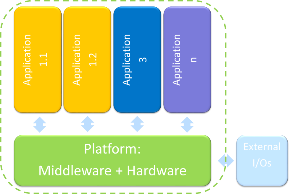 Figure 1 — Illustration of an IMA architecture Note: Examples of different classes of electronic hardware parts constituting a platform/module can be found in ETSO-2C153. Figure 2 shows a functional projection of an IMA architecture at aircraft level: — Each aircraft function may have its own set of LRUs connected to the platform (which provides/gets the data to/from the application). — The set of I/O may cover a large range of items, such as: — input items: data from sensors, control panels, data received from other applications/systems; — output items: data to actuators, displays, and data transmitted to other applications/systems. 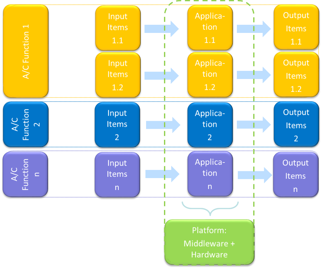 Figure 2 — Functional projection of an IMA architecture at aircraft level An example of an IMA architecture is illustrated in Figure 3. 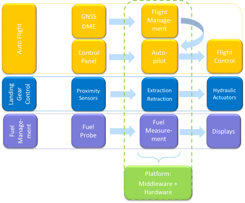 Figure 3 — Illustration of an IMA architecture 2.2. IMA system breakdown into aircraft systems (ATA chapters) The organisation of an IMA system into aircraft systems (e.g. ATA chapters) provides structure to a certification project and to the methods used to demonstrate compliance. This breakdown may depend on (this list is not exhaustive): — the aircraft and systems’ architecture; — the industrial organisation and work sharing; — the applicant’s development methods; and/or — the aircraft maintenance principles and procedures (closely linked to ATA-XX chaptering). Note: Applicants may elect to address the IMA items and activities (not the hosted functions) within an ATA chapter dedicated to IMA systems such as ATA-42. 2.3. IMA certification concerns From a certification viewpoint, the use of an IMA architecture raises the following concerns: — failures or faults of the IMA platforms (including hosted applications) or LRUs connected to the communication network and the associated interfaces may cause the malfunction, loss or partial loss of more than one function; — the potential for some failures to propagate and create multiple failure conditions; — the lack of design independence among common hardware resources; — susceptibility to common mode failures, faults or design errors, within several identical modules or within the communication network; — a lack of assurance that the system will behave as intended once all the hosted applications are integrated onto the platform/modules, when software and electronic hardware items have been independently developed and verified; — inappropriate resource management leading to potential access conflicts and a lack of determinism or unexpected system behaviour; and — improper isolation mechanisms or configuration not ensuring correct partitioning between functions. 2.4. Functional isolation and independence From a safety perspective, the primary purpose of the IMA design and certification activities is to demonstrate that the level of functional isolation and independence between the aircraft functions hosted in the IMA system is equivalent to that which would be achieved in a federated architecture. Functional isolation mostly relies on three pillars: — proper allocation of shared resources, to prevent adverse interference between hosted applications; — robust partitioning, concretely assuring the isolation and detection/mitigation of partitioning violations; — fault containment, to prevent the propagation of faults between hosted applications. 3. Policy for IMA system certification This section provides guidance to be used for the certification of an IMA system. Considering the IMA architecture, industrial organisation, and the experience in IMA system development of the applicant, several approaches are considered: — use of the ED-124 standard; — use of an alternative means to demonstrate compliance; — use of previously recognised IMA certification processes. 3.1. Use of ED-124 3.1.1. Recognition of ED-124 EUROCAE document ED-124 on Integrated Modular Avionics (IMA) Development Guidance and Certification Considerations, published in July 2007 (equivalent to the RTCA document DO-297), provides guidance for the development and certification of IMA systems. The use of ED-124 is acceptable to EASA to support the certification of IMA systems when it is used in conjunction with the additional considerations described in this AMC. 3.1.2. Scope of this AMC with respect to ED-124 ED-124 encompasses various aspects and some concepts which are not compatible with the EASA system or which are considered to be outside the scope of this AMC: — It is not the intent of this AMC to cover the development processes for aircraft functions, even if they are implemented by applications hosted in an IMA system. — In relationship with ED-124, it is not the intent of this AMC to cover: — operational aspects of master minimum equipment lists (MMELs) (ED-124 Chapter 3.9); — considerations for continued airworthiness (ED-124 Chapter 6); — the safety assessment process (ED-124 Chapter 5.1). — The cybersecurity aspects (ED-124 Chapter 5.1.5.8) are not adequate, and should be superseded by the applicable cybersecurity standards as defined in the project certification basis. — Regarding the incremental certification process presented in ED-124: — the ‘letter of acceptance’ concept is not feasible in the EASA context. The certification given by EASA is limited to only a specific aircraft type certification (TC), or to a subsequent aircraft level certification of a system change or in the frame of a supplemental type certificate (STC), or granted through an ETSOA; — the alternate concept of ‘reusable software component (RSC)’ acceptance as described in ED-124 Chapter 4, Table 4, with reference to FAA AC 20-148, is not feasible in the EASA context as it makes use of acceptance letters for software parts. 3.1.3. Clarification and use of ED-124 ED-124 defines a complete ‘end-to-end’ framework and a set of objectives to support the certification of IMA systems, i.e. from the development of software/airborne electronic hardware (SW/AEH) items to aircraft integration. As it covers the complete development and certification of IMA systems, ED-124 may contain some objectives, activities and life cycle data similar to those that apply to a federated architecture, and which may not be IMA-specific. Additionally, some considerations in ED-124 may overlap or may be considered to be addressed by other applicable guidance documents (e.g. ED-79). The way in which ED-124 was written, e.g. by allocating objectives, activities and life cycle data to the various ‘tasks’, should therefore not be interpreted: — as imposing a unique scheme in terms of the project organisation, sequencing of activities and expected life cycle data required to meet the objectives; or — as requesting the duplication of activities or life cycle data. The following sections further explain the flexibility which is inherent in the ED-124 approach and which is fully recognised by EASA. 3.1.3.1. The ED-124 task framework ED-124 structures the IMA development activities by tasks and objectives to be achieved at the AEH/SW/module item level. This framework also suggests a definition of roles and responsibilities of the different stakeholders involved in the IMA system development (e.g. application supplier, IMA system integrator). Figure 4 illustrates a mapping between an IMA system breakdown and the certification tasks of ED-124: 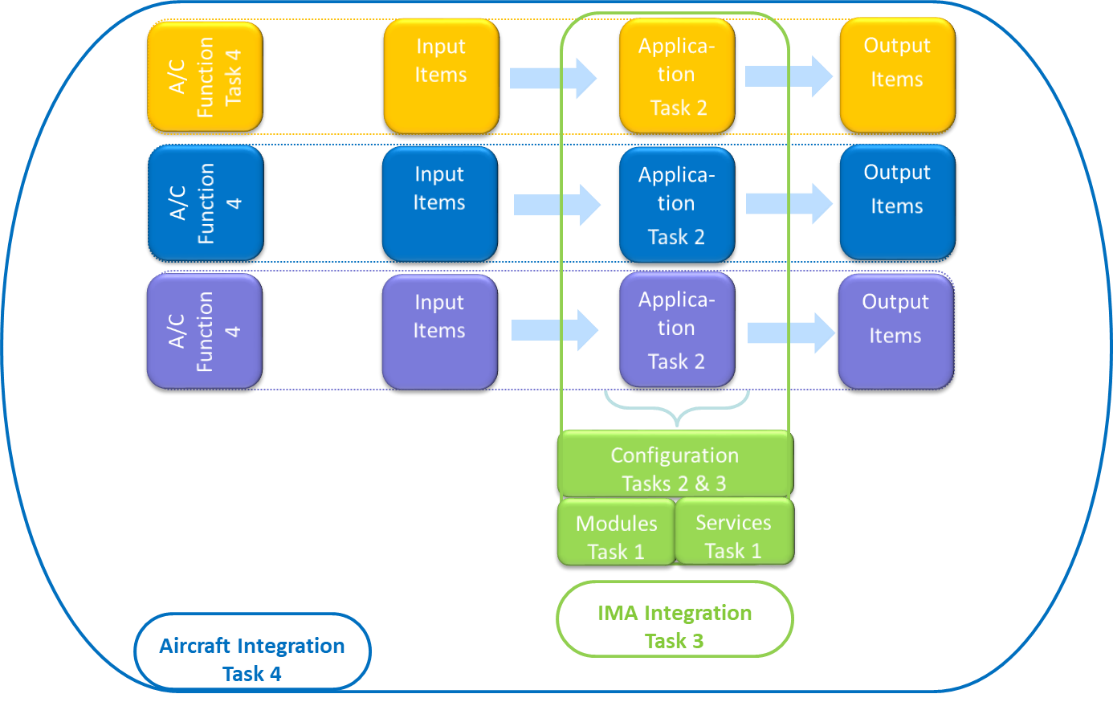 Figure 4 — Mapping between an IMA system and the ED-124 certification tasks Among the considerations detailed in the ED-124 tasks, the key IMA specificities are: — Task 1: the need to develop resources/services to be shared by applications and the adequate associated mechanisms (partitioning, health monitoring, etc.), and the need to document these resources, services and mechanisms for the IMA platform users; — Task 2: the need to characterise the applications in terms of their resource usage and execution constraints, and the need to verify that the applications satisfy the usage domain of the platform; — Task 3: the need to verify that the whole set of applications complies with the platform usage domain, and the proper implementation of the resource allocation and platform configuration requests from the applications; — Task 4: has little specificity in comparison with non-IMA systems. 3.1.3.2. Relationship with other guidelines In order to maximise the credit taken from other standards and existing processes, two certification approaches based on the ED-124 tasks and objectives are considered eligible to support an IMA system certification: (a) an IMA system perspective: by considering the application of ED-124 as a complete and consistent set of objectives; (b) an aircraft perspective: where the IMA system certification and its specificities are addressed within the global framework of the aircraft certification and its related processes. This means that ED-124 considerations/objectives may be covered by other aircraft system processes and activities. As ED-79 provides guidance and acceptable means of compliance for the development of systems, ED-79 processes may be used to cover ED-124 objectives and activities. However, the use of ED-79 will not ensure exhaustive coverage of the ED-124 objectives. Consequently, the IMA-specific objectives and activities of ED-124 will remain to be addressed separately from the ED-79 objectives. These two approaches are suitable because they would ensure the completeness of the activities supporting an IMA system certification.  Figure 5 — Links between ED-124 tasks and other guidelines 3.1.3.3. Tailoring of ED-124 tasks A task framework is proposed by ED-124, but it is not the purpose of AMC 20-170 to enforce this division of tasks. The allocation of the ED-124 objectives to the ED-124 tasks can be tailored by the applicant. For instance, an IMA specificity is the need to coordinate verification activities such that the performance of the integrated IMA system can be guaranteed without requiring the reverification of each hosted application on the entire integrated system: — ED-124 Chapter 3.1.3 d.2 may be interpreted as requesting that IMA integration should be performed with the full set of applications. However, the applicant may integrate and verify applications independently on the IMA platform, taking into account the platform properties (e.g. robust partitioning and resource management). — Some Task 3 objectives may be already anticipated and accomplished during Task 2, or they may be deferred to Task 4. If the applicant intends to develop an IMA system and the supported aircraft functions by tailoring the ED-124 tasks or by following another framework, the applicant should detail the division of tasks, the objectives of each work package, and the associated activities. The applicant should describe how the work package objectives are mapped to the ED-124 objectives in order to ensure that the objectives of ED-124 are met within the alternative framework presented by the applicant. The ED-124 life cycle data can be also adapted to the division of tasks and work packages defined by the applicant. Moreover, ED-124 Task 4 may have few IMA specificities compared to a federated architecture. The achievement of Task 4 to support compliance demonstration in the frame of this AMC could be deemed to be outside the scope of this AMC, provided that: — the aircraft integration activity is covered through other guidance and its related applicant processes (to be clarified in the certification plan); — Task 3 is complete: meaning that no objectives, activities, or life cycle data are deferred to or covered by Task 4. Another area where tailoring can be performed is requirement validation. ED-124 Chapter 5.3.a. considers that each level of requirements within the hierarchy should be validated prior to validating the next lower level. A strict interpretation of this statement would not allow the development of a platform based on the assumptions for the intended use without consideration of the final aircraft functions (as suggested in Chapter 4.2.1.b). Also, it would imply a top-down approach from the aircraft functions to the level of hardware and the core/support software, which may not be relevant. A bottom-up approach is also feasible, which involves ensuring that the platform usage rules and constraints identified in the platform user guide/manual (Chapter 4.2.12.e.) are fulfilled, and that they satisfy the IMA system requirements. 3.1.4. Use of alternative means to demonstrate compliance If an applicant elects to comply with an alternative means to demonstrate compliance with the CS, consistency with the ED-124 acceptance objectives in Annex A tables [A1-A6] (IMA module/platform development process objectives) should be demonstrated. Early coordination with EASA should be ensured. 3.2. Use of previously recognised means of compliance Applicants who did not use this AMC in their past IMA certifications and who successfully used other means of compliance that were: — discussed in specific CRI(s); — previously recognised as equivalent to the ED-124 objectives; and — previously accepted by EASA for covering IMA certification concerns, may use the same means of compliance for their certification project, provided that the IMA system is similar to the previously certified one (i.e. with a similar architecture, the same design concepts, the same development process, and the same certification approach). Early coordination with EASA to confirm the use of the applicant’s previously recognised means of compliance should be ensured. 3.3. Role of the IMA system certification plan ED-124 objectives can be met by using various industrial mappings, based on the sharing of roles, activities and life cycle data. The strategy selected for demonstration of compliance with this AMC should be defined by the applicant in their certification plans. An IMA system certification plan should introduce the planning, the organisation, the work share, work packages, and the development, validation, integration, and verification activities of the IMA system. Considerations regarding the content of an IMA system certification plan can be found in ED-124 Chapter 4.4.3. The certification plan should particularly emphasise the following topics: — The scope covered by the IMA system certification plan and its relationship with other certification plans, including the certification plans of the aircraft functions hosted (totally or partially) on the IMA system. — The strategy proposed by the applicant to demonstrate compliance with this AMC, including: — the certification approach selected (see paragraph 3); — the relationship and credit potentially taken from other standards or processes to satisfy the objectives of ED-124; — the nature and extent of credit claimed from previously approved components (i.e. having obtained an ETSOA) or from activities performed on components reused from previous certification projects (see paragraph 4); — the identification of modules, platforms and applications for which full or partial incremental compliance credit is sought. — The industrial organisation supporting the IMA system development and certification, including the roles, responsibilities and work share between the stakeholders, with, in particular: — the sharing of activities related to aircraft functions hosted on the IMA platform and the IMA system integration activities; — when applicable, the tailoring and scope of the ED-124 tasks, or ED-124 life cycle data; — the work package allocated to each IMA stakeholder, including the design, validation, verification and integration activities, including environmental qualification under their responsibility and the credit claimed for the incremental certification. — The activities planned for the integration of the IMA system and its installation on an aircraft with an emphasis on: — the establishment of full or partial incremental credit gained from the integration, validation and verification activities conducted at each stage of the development, with their associated transition criteria. If a future step cannot be planned by a stakeholder, who for instance would — only perform the development of a function, the interface to future steps and the assumptions made (e.g. on resources used) need to be identified; — the credit expected from the characteristics of the IMA platform to independently verify aircraft functions allocated or partially allocated to the IMA system; — the activities to be completed for the installation of an ETSO-2C153 or C214 article; — the rationale for not performing some ground or flight tests when the IMA system is installed on the aircraft. — A description of the development and verification environments, with emphasis on the tools used to generate data or automate the activities and the rationale for the qualification or non-qualification of the tools. Note: A dedicated IMA system certification plan may not be required provided that its role is equivalently performed by a comprehensive set of documents in the applicant’s data package. 4. Incremental certification process As indicated in Section 3.1.2, the concepts of ‘letters of acceptance’ and of ‘reusable software components (RSCs)’ are not compatible with the EASA system. Furthermore, within the EASA system, there is currently no means to benefit from the certification credit granted within a TC or an STC in the frame of another product certification. Formal compliance credit can only be claimed from an ETSOA. However, the lack of an ETSOA, or the absence of a letter of acceptance, does not prevent an applicant from incrementally building confidence and demonstrating compliance of IMA components during the development flow (as per the ED-124 task framework), nor does it prevent the reuse of previous certification artefacts and activities for a new demonstration of compliance. The incremental certification process is the process to certify a product for which EASA agrees to grant some credit to a component/module, application or system, before that module, application or system is configured, integrated and certified as part of the final product. The incremental certification process applies to the following approaches: (a) Incremental component qualification: credit is taken from activities performed during various steps of the development in order to reduce the effort during a subsequent phase (e.g. verification activities). This qualification is mainly built up using the incremental verification approach. (b) Reuse: credit is taken from activities performed on components (modules, platforms, applications) reused from other projects. This approach encompasses the components reused from a previously approved TC or from legacy IMA systems. (c) Compliance credit: formal credit is claimed from an ETSOA. In all cases, the applicant should evaluate and substantiate the suitability and level of the credit sought. Early coordination with EASA should be ensured. Note: An ETSOA is not a mandatory step in the certification of an IMA system. <table border="1" cellpadding="0" cellspacing="0" width="571"><thead><tr><td colspan="2" width="129"><p align="center"><b>Approach</b></p></td><td width="133"><p align="center"><b>Demonstration of compliance — responsibilities</b></p></td><td width="150"><p align="center"><b>Applicant activities</b></p></td><td width="159"><p align="center"><b>Evidence supporting the claim</b></p></td></tr></thead><tr><td valign="top" width="32"><p>(a)</p></td><td valign="top" width="97"><p>Incremental component qualification</p><p>See paragraph 4.1</p></td><td valign="top" width="133"><p>Under the full responsibility of the applicant*.</p></td><td valign="top" width="150"><p>Full compliance demonstration is expected from the applicant.</p></td><td valign="top" width="159"><p>Evidence of review and acceptance by the applicant, covering all objectives for which credit is sought, including final review reports (at software, hardware, platform, IMA system level(s), as applicable).</p></td></tr><tr><td valign="top" width="32"><p>(b)</p></td><td valign="top" width="97"><p>Reuse from previous TC</p><p>See paragraph 4.2</p></td><td valign="top" width="133"><p>Under the full responsibility of the applicant*.</p></td><td valign="top" width="150"><p>Compliance demonstration may be tailored depending on the agreement with EASA**.</p><p>Note: Demonstration of compliance for the IMA components may be reduced (e.g. no software development and verification reviews (SOI#2&3) as part of Task 2).</p></td><td valign="top" width="159"><p>Previous set of evidence.</p><p>Evidence of review and acceptance by the applicant, covering all objectives for which credit is sought, including final review reports (at software, hardware, platform, IMA system level(s), as applicable).</p></td></tr><tr><td valign="top" width="32"><p>(c)</p></td><td valign="top" width="97"><p>Compliance credit</p><p>See paragraph 4.3</p></td><td valign="top" width="133"><p>Shared between the:</p><p>ETSO holder for the scope covered by the ETSOA (e.g. module/platform);</p><p>applicant* for the completion of integration and/or installation activities. </p></td><td valign="top" width="150"><p>Compliance demonstration is reduced according to the certification credit claimed from the ETSOA.</p></td><td valign="top" width="159"><p>ETSOA</p></td></tr></table> Incremental certification evidence table \* Applicant stands for the applicant developing and/or installing the IMA system. \*\* Discussions held on a case-by-case basis based on the information provided through the certification plan. Whatever the approach selected for the recognition of credit and the level of credit granted, the applicant remains responsible for ensuring and for demonstrating that each component is integrated and installed consistently with its function, interfaces, usage domain, and limitations. 4.1. Incremental component qualification One main characteristic of IMA systems and the ED-124 task framework is that they allow a high level of independence in the design and verification activities: — between the functional level (application) and the resource level (module/platform); — between different applications (except for possible functional coupling between applications). In addition, Chapter 2.2.e of ED-124 introduces the concept of ‘composability’, where the integration of a new application does not invalidate any of the verified requirements of an already integrated application. When an IMA system is ‘composable’, credit can be taken from its properties (e.g. robust partitioning) regarding two aspects: — during the development of the application itself: credit may be taken from module/platform development activities; — during the integration and verification activities: credit may be taken from the integration of the application and from the absence of impact on other already verified and installed applications. These principles drive a modular approach, which can be used to support an incremental component qualification process, provided the following considerations are fulfilled: — The applicant should define criteria and supporting evidence to demonstrate the achievement of all objectives for which credit is sought. — The applicant should assess, and record through a formal review, the achievement and acceptance of a set of objectives for a given component. For instance, a final software and hardware review (SOI#4) on the components of a module and the acceptance of the corresponding software and hardware accomplishment summaries could support the completion of ED-124 Task 1. Depending on the framework and organisation, strict AMC 20-115() or ED-80 compliance may not, on its own, be sufficient to show the achievement of a given task. Complementary accomplishment summaries should be provided and encompassed in the applicant’s review. 4.2. Reuse of components The applicant remains fully responsible for the contents of the associated data, which have to be assessed through the applicant’s activities as being reusable in the context of the current certification project. 4.2.1. Reuse from a legacy IMA system Components that were previously approved may be reused provided that the applicant shows that the reuse of the component is appropriate. If changes are necessary, a change impact analysis should be performed to identify the scope of the changes and the necessary activities to re-engage in to cover the changes. 4.2.2. Reuse from a previous ED-124 project The management of reused components is addressed through ED-124 Task 6 (ED-124 Chapter 4.7). If changes are intended, they should be managed through ED-124 Task 5 (ED-124 Chapter 4.6). Note: To facilitate the reuse of a component, ED-124 recommends developers to anticipate such reuse during the initial development through dedicated objectives that are part of Tasks 1 & 2 (e.g. the module acceptance plan providing the data listed in Chapter 4.2.3.h). 4.3. Compliance credit In the frame of this AMC, formal certification credit is offered from an ETSOA granted to: — platform(s)/module(s): ETSO-2C153; — application(s) integrated with an ETSO-2C153 module/platform: ETSO-C214. 4.3.1. Use of an ETSO-2C153 authorisation An ETSO-2C153 can be granted to a platform(s)/module(s) in order to facilitate its (their) use in an IMA system. As per ETSO-2C153 paragraph 3.2.2.1, the IMA module or platform should meet the ED-124 Task 1 objectives. Compliance credit could be hence claimed by an applicant for the demonstration of compliance with ED-124 Task 1, provided the platform(s)/module(s) had obtained an ETSO-2C153 authorisation beforehand. Nevertheless, the ETSOA does not by itself ensure that the platform(s)/module(s) is (are) technically adequate to be integrated into the IMA system. The applicant remains responsible for all the activities to ensure the proper integration of the ETSO-2C153 platform(s)/module(s) into the IMA system, and the applicant should: — substantiate the scope of the ETSOA compliance credit, and define the complementary certification activities based on the data provided (e.g. user/installation manuals); — demonstrate the correct use of the platform(s)/module(s), including compliance: — with the platform/module integration requirements/user requirements, and the IMA system and safety requirements; — of the use, the partitioning, the health monitoring, the configuration of the resources and the installation of the items with the platforms/modules user guide/manual, installation manual, or equivalent data (as documented per ETSO-2C153 Appendix 3). This also includes the deactivation or disabling of unused ETSO-2C153 functions/modules, when available, or the means to ensure that the intended function is performed without any interference from unused ETSO-2C153 functions/ modules. This section only addresses the use of EASA ETSO-2C153, and its use cannot be extended to any other authority TSO standards on IMA platforms and modules that are not equivalent in their technical requirements. 4.3.2. Use of a functional ETSO-C214 authorisation Through a functional ETSO-C214 (F-ETSO), an authorisation can be granted to application(s) integrated with an ETSO-2C153 module/platform. As per ETSO-C214, compliance with the ED-124 Task 2 & 3 objectives has to be demonstrated. Compliance credit could hence be claimed by an applicant for the demonstration of compliance with ED-124 Tasks 2 & 3, provided that the F-ETSO-C214 authorisation had been obtained beforehand. Nevertheless, the functional ETSOA does not by itself ensure that the ETSO article is technically adequate to be installed in the product. The applicant remains responsible for all the activities to ensure the proper integration of the application(s)/module(s)/platform(s) into the IMA system, and the applicant should: — substantiate the scope of the ETSOA compliance credit, and define the complementary certification activities; — complete the demonstration that the function covered by the F-ETSO article complies with the IMA system and safety requirements. If the F-ETSO article is in the ‘open’ class and the applicant intends to perform incremental development on the ETSOA article (e.g. to add an application), the considerations of this AMC apply to the new and affected items. The applicant should ensure the integrity and continuity of the system configuration, and in particular should show that the resource allocation, partitioning, and health monitoring are not impaired by the intended changes to the ETSOA article. The level of credit that can be obtained from the F-ETSO article, and the certification activities to be completed in the frame of this AMC, will hence vary depending on the scope of the changes made to the initial F-ETSO article. If the F-ETSO article is in the ‘closed’ class, it no longer offers any capability for IMA development. Credit can be taken for ED-124 Tasks 2 and 3. This closed F-ETSO article is equivalent to a conventional ETSO article. 4.3.3. Summary of ETSO compliance credit The following table summarises the credit that can be claimed from ETSO-2C153 and ETSO-C214, and the remaining certification activities to support the demonstration of compliance with AMC 20-170: <table border="1" cellpadding="0" cellspacing="0" width="495"><tr><td valign="top" width="180"><p align="center"><b>ETSOA</b></p></td><td valign="top" width="144"><p align="center"><b>Credit</b></p></td><td valign="top" width="170"><p align="center"><b>Remaining activities</b></p></td></tr><tr><td valign="top" width="180"><p align="center">ETSO-2C153</p><p><div class="image-container"><img alt="EASA EAR image" src="/static/files/file_ftLzkYEblJP/image077.png"/></div></p></td><td valign="top" width="144"><p align="center">Acceptance of the platform/module</p><p align="center">(ED-124 Task 1)</p></td><td valign="top" width="170"><p>Substantiation of the scope of ETSOA compliance credit.</p><p>All subsequent activities (ED-124 Tasks 2 and 3, plus those deferred to Task 4).</p></td></tr><tr><td valign="top" width="180"><p align="center">ETSO-C214 ‘open’ class</p><p align="center"><div class="image-container"><img alt="EASA EAR image" src="/static/files/file_ftLzkYEblJP/image078.png"/></div></p></td><td valign="top" width="144"><p align="center">Acceptance of the platform/module</p><p align="center">(ED-124 Task 1)</p><p align="center">Acceptance of the non-impacted hosted application(s)</p><p align="center">(ED-124 Task 2)</p></td><td valign="top" width="170"><p>Substantiation of the scope of ETSOA compliance credit.</p><p>Demonstration that the F-ETSO article complies with the IMA system and safety requirements.</p><p>All activities impacted by the incremental development, such as on the modified or new hosted application (ED-124 Tasks 2), and IMA configuration and integration (ED-124 Task 3 plus those deferred to Task 4.)</p></td></tr><tr><td valign="top" width="180"><p align="center">ETSO-C214 ‘closed’ class</p><p align="center"><div class="image-container"><img alt="EASA EAR image" src="/static/files/file_ftLzkYEblJP/image079.png"/></div></p></td><td valign="top" width="144"><p align="center">Acceptance of the platform/module</p><p align="center">(ED-124 Task 1)</p><p align="center">Acceptance of the hosted application(s)</p><p align="center">(ED-124 Task 2)</p><p align="center">IMA configuration and integration</p><p align="center">(ED-124 Task 3)</p></td><td valign="top" width="170"><p>Substantiation of the scope of ETSOA compliance credit.</p></td></tr></table> ETSO compliance credit table for AMC 20-170 5. Additional recommendations for IMA system certification 5.1. Fault management and human factors ED-124 Chapter 3.6.5 deals with the annunciation of failures to the crew. CS XX.1322 and the associated AMC address flight crew alerting systems and warning, caution, or advisory lights. In any case where an inconsistency is identified between the text in ED-124 and the text in CS XX.1322 and the associated AMC, the text in CS XX.1322 and the associated AMC should prevail. Similarly, for any inconsistency between the text in ED-124 Chapter 3.10 dealing with human factors and the text in CS XX.1302 and the associated AMC, the text in CS XX.1302 and the associated AMC should prevail. 5.2. Configuration data/parameter data items Guidance on IMA configuration data is provided in ED-124 Chapter 3.7.1.1 at the IMA system level and in Chapter 3.7.1.2 at the application level. These data items are nowadays described as ‘parameter data items’ as defined in ED-12C and should be treated in the same way as other elements of the software. Depending on how a parameter data item is to be used in the IMA system or application, it needs to be defined, managed and documented at the appropriate level (platform, module, application) and to comply with the AMC 20-115()[[50]](#_ftn50) guidance, including the process to ensure intermixability and compatibility during the post-TC period as indicated in ED-124. In particular, any parameter data item should be assigned the same software level as the component using it. 5.3. Use of tools and the need for qualification IMA system development may be supported by the use, at the system level, of tools in order to eliminate, reduce, or automate the activities associated with the ED-124 objectives. If a tool could introduce an error or could fail to detect an error, and there are no other alternative means to detect the issue, qualification of the tool is needed. For instance, a tool may be used to generate and/or verify IMA configuration data and may produce an erroneous configuration that is not necessarily easily detectable at a subsequent integration/verification step. The objectives of tool qualification are to: — ensure an equivalent level of confidence to the non-automated process/activities; — demonstrate that the tool complies, and its qualification is commensurate, with the intended use. Adequate guidance for tool qualification is provided in ED-215, Software Tool Qualification Considerations, and should be followed when a tool is intended to be qualified to support the IMA system development. The following criteria should be used to determine the appropriate tool qualification level (TQL), according to its intended use: (a) Impact of the tool: (1) Criterion 1: a tool whose output is part of the IMA system and thus could introduce an error. (2) Criterion 2: a tool that automates verification process(es) and thus could fail to detect an error, and whose output is used to justify the elimination or reduction of: — verification process(es) other than that (those) automated by the tool; or — development process(es) that could have an impact on the IMA system. (3) Criterion 3: a tool that, within the scope of its intended use, could fail to detect an error. (b) IDAL of the IMA component supported by the tool: <table border="1" cellpadding="0" cellspacing="0" width="493"><thead><tr><td rowspan="2" width="123"><p align="center"><b>IDAL</b></p></td><td colspan="3" width="370"><p align="center"><b>Criteria</b></p></td></tr><tr><td width="123"><p align="center"><b>1</b></p></td><td width="123"><p align="center"><b>2</b></p></td><td width="123"><p align="center"><b>3</b></p></td></tr></thead><tr><td valign="top" width="123"><p align="center">A</p></td><td valign="top" width="123"><p align="center">TQL-1</p></td><td valign="top" width="123"><p align="center">TQL-4</p></td><td valign="top" width="123"><p align="center">TQL-5</p></td></tr><tr><td valign="top" width="123"><p align="center">B</p></td><td valign="top" width="123"><p align="center">TQL-2</p></td><td valign="top" width="123"><p align="center">TQL-4</p></td><td valign="top" width="123"><p align="center">TQL-5</p></td></tr><tr><td valign="top" width="123"><p align="center">C</p></td><td valign="top" width="123"><p align="center">TQL-3</p></td><td valign="top" width="123"><p align="center">TQL-5</p></td><td valign="top" width="123"><p align="center">TQL-5</p></td></tr><tr><td valign="top" width="123"><p align="center">D</p></td><td valign="top" width="123"><p align="center">TQL-4</p></td><td valign="top" width="123"><p align="center">TQL-5</p></td><td valign="top" width="123"><p align="center">TQL-5</p></td></tr></table> 5.4. Change management This section deals not only with changes to components that were previously accepted through a TC, STC or ETSOA, but also with changes during the development as soon as components are delivered for use in a subsequent stage of the process and a formal baseline is established for these components. The main objectives of the change management process are to conduct and document a change impact analysis and to reintegrate the changed component into the IMA system, performing all the necessary verification, validation, and integration activities (including regression analysis and testing). (a) Since there are various levels of development and integration in an IMA system, and potentially various stakeholders (the module/platform developer, application developer, IMA system integrator, aircraft designer), agreements should be concluded between stakeholders to establish the way to communicate changes and to perform impact analyses at each level. (b) A change impact analysis should consider the possible impacts to be reported at each relevant level: — changes at the resource allocation level; — changes at the module/platform level; — changes at the application level. (c) Impacts on incremental compliance credit (if applicable) also need to be considered. (d) The changes should be documented in the appropriate life cycle data, including the trace data, configuration indexes and accomplishment summaries. 5.5. Management of problem reports IMA systems contain multiple applications hosted on the same IMA module/platform, therefore any OPR related to a module/platform or application, collected at any level, could affect one or several aircraft functions directly or indirectly. Considering the diversity of stakeholders in an IMA system, the management of problem reports can be more complex than with federated systems. In addition to the applicable guidance on OPR management, for IMA systems, the applicant should organise the management of OPRs, focusing on: — the evaluation of the potential effect of each OPR on any shared resources and IMA services, and the evaluation of those OPRs for impact on any aircraft function that uses the affected shared resources and IMA services; — the verification that necessary workarounds, including limitations, at the application and/or system levels, are documented within the IMA documentation (e.g. user guide/manual). In such cases, the efficiency of a workaround should be substantiated and the successful (i.e. complete and correct) deployment of the workaround should be ensured. NOTE: In order to facilitate the assessment and the communication between stakeholders, the use of a harmonised classification scale for OPRs is recommended. 5.6. Environmental qualification The scope of this section is to provide environmental qualification guidance complementary to ED-124 Chapter 5.2.6 for the environmental qualification of an IMA system. It can be an IMA platform composed of only one LRU, or various modules in a given configuration. The platform is qualified in conditions of the same severity as those expected when installed on the aircraft, interfaced with its peripherals through the aircraft (or equivalent) harnesses, and loaded with its set of applications. The acceptance criteria to qualify the platform are driven by the operational requirements of a given aircraft. Level of qualification testing activities: The modularity of an IMA platform makes it possible to conduct qualification testing activities at various stages: — IMA module testing: the testing is performed on an IMA module, involving the shared resources (hardware and/or software), and when relevant, with a representative set of software applications loaded onto the module. In the case of a cabinet, the module can be a chassis and/or a backplane. — IMA platform testing: the testing is performed on the platform or cabinet (chassis and backplane) equipped with its modules, and when relevant, loaded with a representative set of software applications. — System testing: the testing is performed on a set of modules and/or the backplane installed in the cabinet, with system peripherals interfaced with the cabinet, and with representative software applications loaded onto the modules. — Aircraft testing: the testing is performed with the systems installed on the aircraft. The modularity of the IMA platform, combined with the variety of its possible configurations, leads to the establishment of principles to reuse qualification credit for IMA modules in the context of qualifying a desired IMA platform for a given aircraft: (a) The environmental usage domain of an IMA module is the set of environmental conditions for which it is qualified. This is documented in the module user guide/manual. (b) For an IMA module integrated within a cabinet, its environmental qualification conditions should consider: — its environmental conditions (i.e. the envelope of thermal, electromagnetic, vibration, lightning, etc., conditions) encountered inside the cabinet when in use on the aircraft; — all its possible arrangements in the cabinet (i.e. different IMA platform configurations). Incremental environmental qualification is an approach used in qualifying a cabinet populated with modules in a known configuration for a given aircraft, relying on existing qualification credit for IMA modules in their environmental usage domain, and identifying any complementary qualification substantiation that would be necessary to cover the envelope of the environmental conditions of the aircraft. Thus it provides the latitude to populate a cabinet with already qualified modules, to qualify it without having to perform a full reassessment of the qualification of each module, and the capability to reuse its existing qualification dossier. All the substantiation data recorded in the qualification plan should be based on dedicated tests or on equivalence with the reuse of existing qualification results, or existing authorisations such as ETSO-2C153. The representativeness of the substantiation should consider the testing configuration, the testing conditions (including electrical, thermal, mechanical interfaces, etc.), the qualification testing level, the application software used for the testing, the test scenario and the level of stress applied. When an IMA system change is implemented, a change impact analysis should be conducted against the qualified configuration to assess the complementary qualification substantiation to be provided for each of its modules. [Amdt 20/15] --- [[50]](#_ftnref50) Starting from AMC 20-115D.