AMC1 Article 11 Rules for conducting an operational risk assessment
ED Decision 2023/012/R
SPECIFIC OPERATIONS RISK ASSESSMENT (SORA) (SOURCE JARUS SORA V2.0)
EDITION December 2020
1. Introduction
1.1 Preface
(a) This SORA is based on the document developed by JARUS, providing a vision on how to safely create, evaluate and conduct an unmanned aircraft system (UAS) operation. The SORA provides a methodology to guide both the UAS operator and the competent authority in determining whether a UAS operation can be conducted in a safe manner. The document should not be used as a checklist, nor be expected to provide answers to all the challenges related to the integration of the UAS in the airspace. The SORA is a tailoring guide that allows a UAS operator to find a best fit mitigation means, and hence reduce the risk to an acceptable level. For this reason, it does not contain prescriptive requirements, but rather safety objectives to be met at various levels of robustness, commensurate with the risk.
(b) The SORA is meant to inspire UAS operators and competent authorities and highlight the benefits of a harmonised risk assessment methodology. The feedback collected from real‑life UAS operations will form the backbone of the updates in the upcoming revisions of the document.
1.2 Purpose of the document
(a) The purpose of the SORA is to propose a methodology to be used as an acceptable means to demonstrate compliance with Article 11 of the UAS Regulation, that is to evaluate the risks and determine the acceptability of a proposed operation of a UAS within the ‘specific’ category.
(b) Due to the operational differences and the expanded level of risk, the ‘specific’ category cannot automatically take credit for the safety and performance data demonstrated with the large number of UA operating in the ‘open[13]’ category. Therefore, the SORA provides a consistent approach to assess the additional risks associated with the expanded and new UAS operations that are not covered by the ‘open’ category.
(c) The SORA is not intended as a one-stop-shop for the full integration of all types of UAS in all classes of airspace.
(d) This methodology may be applied where the traditional approach to aircraft certification (approving the design, issuing an airworthiness approval and type certificate) may not be appropriate due to an applicant’s desire to operate a UAS in a limited or restricted manner. This methodology may also support the activities necessary to determine the associated airworthiness requirements. This assumes that the safety objectives set forth in, or derived from, those applicable for the ‘certified’[14] category, are consistent with the ones set forth or derived for the ‘specific’ category.
(e) The methodology is based on the principle of a holistic/total system safety risk-based assessment model used to evaluate the risks related to a given UAS operation. The model considers the nature of all the threats associated with a specified hazard, the relevant design, and the proposed operational mitigations for a specific UAS operation. The SORA then helps to evaluate the risks systematically, and determine the boundaries required for a safe operation. This method allows the applicant to determine the acceptable risk levels, and to validate that those levels are complied with by the proposed operations. The competent authority may also apply this methodology to gain confidence that the UAS operator can conduct the operation safely.
(f) To avoid repetitive individual approvals, EASA will apply the methodology to define ‘standard scenarios’ or ‘predefined risk assessments’ for the identified types of ConOps with known hazards and acceptable risk mitigations.
(g) The methodology, related processes, and values proposed in this document are intended to guide the UAS operator when performing a risk assessment in accordance with Article 11 of the UAS Regulation.
1.3 Applicability
(a) The methodology presented in this document is aimed at evaluating the safety risks involved with the operation of UAS of any class, size or type of operation (including military, experimental, research and development and prototyping). It is particularly suited, but not limited to, ‘specific’ operations for which a hazard and a risk assessment are required.
(b) The safety risks associated with collisions between UA and manned aircraft are in the scope of the methodology. The risk of a collision between two UA or between a UA and a UA carrying people will be addressed in future revisions of the document.
(c) In the event of a mishap, the carriage of people or payloads on board the UAS (e.g. weapons) that present additional hazards is explicitly excluded from the scope of this methodology.
(d) Security aspects are excluded from the applicability of this methodology when they are not limited to those confined by the airworthiness of the systems (e.g. the aspects relevant to protection from unlawful electromagnetic interference.)
(e) Privacy and financial aspects are excluded from the applicability of this methodology.
(f) The SORA can be used to support waiving the regulatory requirements applicable to the operation if it can be demonstrated that the operation can be conducted with an acceptable level of safety.
(g) In addition to performing a SORA in accordance with the UAS Regulation, the UAS operator must also ensure compliance with all the other regulatory requirements applicable to the operation that are not necessarily addressed by the SORA.
1.4 Key concepts and definitions
1.4.1 Semantic model
(a) To facilitate effective communication of all aspects of the SORA, the methodology requires the standardised use of terminology for the phases of operation, procedures, and operational volumes. The semantic model shown in Figure 1 provides a consistent use of the terms for all SORA users. Figure 2 provides a graphical representation of the model and a visual reference to further aid the reader in understanding the SORA terminology.
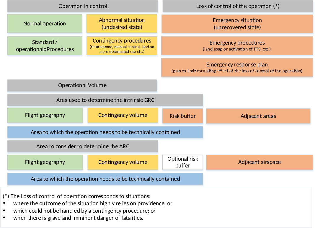
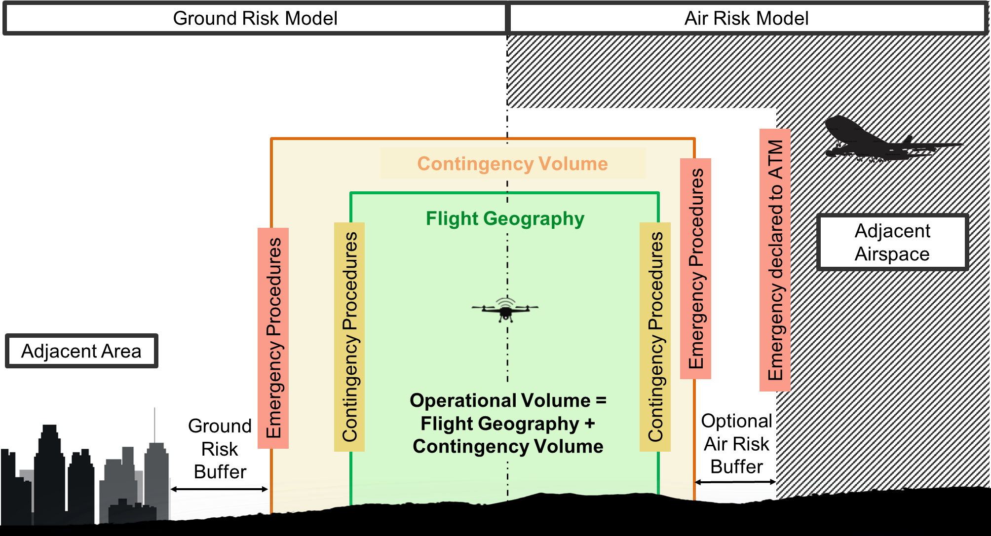
Figure 2 —
Graphical representation of the SORA semantic model
1.4.2 Introduction to robustness
(a) To properly understand the SORA process, it is important to introduce the key concept of robustness. Any given risk mitigation or operational safety objective (OSO) can be demonstrated at differing levels of robustness. The SORA process proposes three different levels of robustness: low, medium and high, commensurate with the risk.
(b) The robustness designation is achieved using both the level of integrity (i.e. safety gain) provided by each mitigation, and the level of assurance (i.e. method of proof) that the claimed safety gain has been achieved. These are both risk-based.
(c) The activities used to substantiate the level of integrity are detailed in Annexes B, C, D and E. Those annexes provide either guidance material or reference industry standards and practices where applicable.
(d) General guidance for the level of assurance is provided below:
(1) A low level of assurance is where the applicant simply declares that the required level of integrity has been achieved.
(2) A medium level of assurance is where the applicant provides supporting evidence that the required level of integrity has been achieved. This is typically achieved by means of testing (e.g. for technical mitigations) or by proof of experience (e.g. for human-related mitigations).
(3) A high level of assurance is where the achieved integrity has been found to be acceptable by a competent third party.
(e) The specific criteria defined in the Annexes take precedence over the criteria defined in paragraph d.
(f) Table 1 provides guidance to determine the level of robustness based on the level of integrity and the level of assurance:
|
|
Low assurance |
Medium
assurance |
High assurance |
|
Low integrity |
Low robustness |
Low robustness |
Low robustness |
|
Medium
integrity |
Low robustness |
Medium robustness |
Medium robustness |
|
High integrity |
Low robustness |
Medium robustness |
High robustness |
Table 1 —
Determination of robustness level
(g) For example, if an applicant demonstrates a medium level of integrity with a low level of assurance, the overall robustness will be considered to be low. In other words, the robustness will always be equal to the lowest level of either the integrity or the assurance.
1.5 Roles and responsibilities
(a) While performing a SORA process and assessment, several key actors might be required to interact in different phases of the process. The main actors applicable to the SORA are described in this section.
(b) UAS operator — The UAS operator is responsible for the safe operation of the UAS, and hence the safety risk analysis. In accordance with Article 5 of the UAS Regulation, the UAS operator must substantiate the safety of the operation by performing the specific operational and risk assessment, except for the cases defined by the same Article 5. Supporting material for the assessment may be provided by third parties (e.g. the manufacturer of the UAS or equipment, U-space service providers, etc.). The UAS operator obtains an operational authorisation from the competent authority/ANSP. A UAS operator having a LUC cannot be granted the privilege to assess compliance with the design requirements when a UAS with a design verification report[15] (DVR) or a (restricted) type certificate ((R)TC) is required.
(c) Applicant — The applicant is the party seeking operational approval. The applicant becomes the UAS operator once the operation has been approved.
(d) UAS manufacturer — For the purposes of the SORA, the UAS manufacturer is the party that designs and/or produces the UAS. The UAS manufacturer has unique design evidence (e.g. for the system performance, the system architecture, software/hardware development documentation, test/analysis documentation, etc.) that they may choose to make available to one or many UAS operator(s) or to the competent authority to help to substantiate the UAS operator’s safety case. Alternatively, a potential UAS manufacturer may utilise the SORA to target design objectives for specific or generalised operations. To obtain airworthiness approval(s), these design objectives could be complemented by the use of certification specifications (CS) or industry consensus standards if they are found to be acceptable by EASA.
(e) Component manufacturer — The component manufacturer is the party that designs and/or produces components for use in UAS operations. The component manufacturer has unique design evidence (e.g. for the system performance, the system architecture, software/hardware development documentation, test/analysis documentation, etc.) that they may choose to make available to one or many UAS operator(s) to substantiate a safety case.
(f) Competent authority — The competent authority that is referred to throughout this AMC is the authority designated by the Member State in accordance with Article 17 of the UAS Regulation to assess the safety case of UAS operations and to issue the operational authorisation in accordance with Article 12 of the UAS Regulation. The competent authority may accept an applicant’s SORA submission in whole or in part. Through the SORA process, the applicant may need to consult with the competent authority to ensure the consistent application or interpretation of individual steps. The competent authority must perform oversight of the UAS operator in accordance with paragraphs (i) and (j) of Article 18 of the UAS Regulation. According to Regulation (EU) 2018/1139[16] (the EASA ‘Basic Regulation’), EASA is the competent authority in the European Union to verify compliance of the UAS design and its components with the applicable rules, while the authority that is designated by the Member State is the competent authority to verify compliance with the operational requirements and compliance of the personnel’s competency with those rules. The following elements are related to the UAS design:
— OSOs #02 (limited to design criteria), #04, #05, #06, #10, #12, #18, #19 (limited to criterion #3), #20, #23 (limited to criterion #1) and #24;
— M2 mitigation for ground risk (criterion #1);
— verification of the system to contain the UAS to avoid an infringement of the adjacent areas on the ground and/or adjacent airspace, in accordance with Step #9 of the SORA process.
If the UAS operation is classified as SAIL V and VI, compliance with the design provisions defined by SORA (i.e. design-related OSOs, mitigation means linked with the design and containment function) should be demonstrated through a type certificate (TC) issued by EASA according to Annex I (Part 21) to Regulation (EU) No 748/2012[17] as defined in Article 40(1)(d) of Regulation (EU) 2019/945[18]. For the other OSOs and mitigation means, the competent authority may verify compliance or may define which entity is able to verify compliance with them as a third party.
(1) If the UAS operation is classified as SAIL IV, compliance with the design-related SORA provisions (i.e. design-related OSOs, mitigation means linked with the design and containment function) should be demonstrated through a DVR issued by EASA. Evidence of compliance with the other OSOs and mitigations (not related to design) will be provided to the competent authority according to the level of robustness of the OSOs, that will assess them as part of the application for the operational authorisation.
(2) If the UAS operation is classified as SAIL I, II or III, the competent authority may accept a declaration submitted by the UAS operator for the compliance with all OSOs and mitigations related to design. The competent authority may check the statements of the UAS operator, in particular with regard to the claimed level of integrity and robustness of the UAS for the considered SAIL.
(3) Despite the SAIL, when the claimed level of robustness of the mitigation means M2 is high, the competent authority should require the operator to use a UAS with a DVR issued by EASA limited to compliance with those mitigation means[19].
(g) ANSP — The ANSP is the designated provider of air traffic service in a specific area of operation (airspace). The ANSP assesses whether the proposed flight can be safely conducted in the particular airspace that it covers, and if so, authorises the flight.
(h) U-space service provider — U-space service providers are entities that provide services to support the safe and efficient use of airspace.
(i) Remote pilot — The remote pilot is designated by the UAS operator, or, in the case of general aviation, the aircraft owner, as being charged with safely conducting the flight.
2. The SORA process
2.1 Introduction to risk
(a) Many definitions of the word ‘risk’ exist in the literature. One of the easiest and most understandable definitions is provided in SAE ARP 4754A / EUROCAE ED-79A: ‘the combination of the frequency (probability) of an occurrence and its associated level of severity’. This definition of ‘risk’ is retained in this document.
(b) The consequence of an occurrence will be designated as harm of some type.
(c) Many different categories of harm arise from any given occurrence. Various authors on this topic have collated these categories of harm as supported by the literature. This document will focus on occurrences of harm (e.g. a UAS crash) that are short-lived and usually give rise to a near loss of life. Chronic events (e.g. toxic emissions over a period of time) are explicitly excluded from this assessment. The categories of harm in this document are the potential for:
(1) fatal injuries to third parties on the ground;
(2) fatal injuries to third parties in the air; or
(3) damage to critical infrastructure.
(d) It is acknowledged that the competent authorities, when appropriate, may consider additional categories of harm (e.g. the disruption of a community, environmental damage, financial loss, etc.). This methodology could also be used for those categories of harm.
(e) Several studies have shown that the amount of energy needed to cause fatal injuries, in the case of a direct hit, is extremely low (i.e. in the region of few dozen Joules.) The energy levels of operations addressed within this document are likely to be significantly higher, and therefore the retained harm is the potential for fatal injuries. By application of the methodology, the applicant has the opportunity to claim lower lethality either on a case‑by-case basis, or systematically if allowed by the competent authorities (e.g. in the ‘open’ category).
(f) Fatal injury is a well-defined condition and, in most countries, is known by the authorities. Therefore, the risk of under-reporting fatalities is almost non-existent. The quantification of the associated risk of fatality is straightforward. The usual means to measure fatalities is by the number of deaths within a particular time interval (e.g. the fatal accident rate per million flying hours), or the number of deaths for a specified circumstance (e.g. the fatal accident rate per number of take-offs).
(g) Damage to critical infrastructure is a more complex condition. Therefore, the quantification of the associated risks may be difficult and subject to cooperation with the organisation responsible for the infrastructure.
2.2 SORA process outline
(a) The SORA methodology provides a logical process to analyse the proposed ConOps and establish an adequate level of confidence that the operation can be conducted with an acceptable level of risk. There are ten steps that support the SORA methodology and each of these steps is described in the following paragraphs and further detailed, when necessary, in the relevant annexes.
(b) The SORA focuses on the assessment of air and ground risks. In addition to air and ground risks, an additional risk assessment of critical infrastructure should also be performed. This should be done in cooperation with the organisation responsible for the infrastructure, as they are most knowledgeable of those threats. Figure 3 outlines the ten steps of the risk model, while Figure 4 provides an overall understanding of how to arrive at an air risk class (ARC) for a given operation.
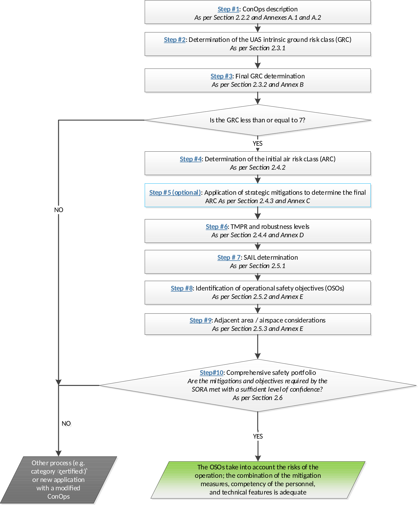
Figure 3 — The SORA process
Note: If operations are conducted across different environments, some steps may need to be repeated for each particular environment.
2.2.1 Pre-application evaluation
(a) Before starting the SORA process, the applicant should verify that the proposed operation is feasible (i.e. not subject to specific exclusions from the competent authority or subject to an STS). Things to verify before beginning the SORA process are whether:
(1) the operation falls under the ‘open’ category;
(2) the operation is covered by a ‘standard scenario’ included in the appendix to the UAS Regulation or by a ‘predefined risk assessment’ published by EASA;
(3) the operation falls under the ‘certified’ category; or
(4) the operation is subject to a specific NO-GO from the competent authority.
If none of the above cases applies, the SORA process should be applied.
2.2.2 Step #1 — ConOps description
(a) The first step of the SORA requires the applicant to collect and provide the relevant technical, operational and system information needed to assess the risk associated with the intended operation of the UAS. Annex A to this document provides a detailed framework for data collection and presentation. The ConOps description is the foundation for all other activities, and it should be as accurate and detailed as possible. The ConOps should not only describe the operation, but also provide insight into the UAS operator’s operational safety culture. It should also include how and when to interact with the ANSP. Therefore, when defining the ConOps, the UAS operator should give due consideration to all the steps, mitigations and OSOs provided in Figures 3 and 4.
(b) Developing the ConOps can be an iterative process; therefore, as the SORA process is applied, additional mitigations and limitations may be identified, requiring additional associated technical details, procedures, and other information to be provided/updated in the ConOps. This should culminate in a comprehensive ConOps that fully and accurately describes the proposed operation as envisioned.
2.3 The ground risk process
2.3.1 Step #2 – Determination of the intrinsic UAS ground risk class (GRC)
(a) The intrinsic UAS ground risk relates to the risk of a person being struck by the UAS (in the case of a loss of UAS control with a reasonable assumption of safety).
(b) To establish the intrinsic GRC, the applicant needs the maximum UA characteristic dimension (e.g. the wingspan for a fixed-wing UAS, the blade diameter for rotorcraft, the maximum dimension for multi-copters, etc.) and the knowledge of the intended operational scenario.
(c) The applicant needs to have defined the area at risk when conducting the operation (also called the ‘area of operation’) including:
(1) the operational volume, which is composed of the flight geography and the contingency volume. To determine the operational volume, the applicant should consider the position-keeping capabilities of the UAS in 4D space (latitude, longitude, height and time). In particular, the accuracy of the navigation solution, the flight technical error[20] of the UAS and the path definition error (e.g. map errors), and latencies should be considered and addressed in this determination;
(2) whether or not the area is a controlled ground area; and
(3) the associated ground risk buffer with at least a 1:1 rule[21], or for rotary wing UA, defined using a ballistic methodology approach acceptable to the competent authority.
(d) Table 2 illustrates how to determine the intrinsic ground risk class (GRC). The intrinsic GRC is found at the intersection of the applicable operational scenario and the maximum UA characteristic dimension that drives the UAS lethal area. If there is a mismatch between the maximum UAS characteristic dimension and the typical kinetic energy expected, the applicant should provide substantiation for the chosen column.
|
Intrinsic UAS
ground risk class |
||||
|
Max UAS characteristics dimension |
1 m / approx. 3 ft |
3 m / approx. 10 ft |
8 m / approx. 25 ft |
>8 m / approx. 25 ft |
|
Typical kinetic energy expected |
< 700 J (approx. 529 ft lb) |
< 34 kJ (approx. 25 000 ft lb) |
< 1 084 kJ (approx. 800 000 ft lb) |
> 1 084 kJ (approx. 800 000 ft lb) |
|
Operational scenarios |
||||
|
VLOS/BVLOS over a controlled ground area[22] |
1 |
2 |
3 |
4 |
|
VLOS over a sparsely populated area |
2 |
3 |
4 |
5 |
|
BVLOS over a sparsely populated area |
3 |
4 |
5 |
6 |
|
VLOS over a populated area |
4 |
5 |
6 |
8 |
|
BVLOS over a populated area |
5 |
6 |
8 |
10 |
|
VLOS over an assembly of people |
7 |
|||
|
BVLOS over an assembly of people |
8 |
|||
Table
2 — Determination of the intrinsic GRC
(e) The operational scenarios describe an attempt to provide discrete categorisations of operations with increasing numbers of people at risk. In principle, it is possible to use either qualitative criteria (please refer to next point (f)) or quantitative criteria, or consider both criteria, to assess if an operation takes place over sparsely populated areas, populated areas, or assemblies of people.
(f) Qualitative assessment: the volume to be used by the operator to classify the operation includes the operational volume and the ground risk buffer (as defined by a semantic model), which determine the intrinsic GRC.
GM1 Article 2(3) ‘Definitions I DEFINITION OF ‘ASSEMBLIES OF PEOPLE’’ provides guidance on when an operation is classified as taking place over assemblies of people.
An operation should be classified as taking place over a populated area if the volume that is used to determine the intrinsic GRC:
— does not include assemblies of people, and
— includes areas that are substantially used for residential, commercial or recreational purposes.
(g) EVLOS[23] operations are to be considered to be BVLOS for the intrinsic GRC determination.
(h) Controlled ground areas[24] are a way to strategically mitigate the risk on ground (similar to flying in segregated airspace); the UAS operator should ensure, through appropriate procedures, that no uninvolved person is in the area of operation, as defined in Section 2.3.1(c).
(i) An operation occurring in a populated environment cannot be intrinsically classified as being in a sparsely populated environment, even in cases where the footprint of the operation is completely within special risk areas (e.g. rivers, railways, and industrial estates). The applicant can make the claim for a lower density and/or shelter with Step #3 of the SORA process.
(j) Operations that do not have a corresponding intrinsic GRC (i.e. grey cells on the table) are not supported by the SORA methodology.
(k) When evaluating the typical kinetic energy expected for a given operation, the applicant should generally use the airspeed, in particular Vcruise for fixed-wing aircraft and the terminal velocity for other aircraft. Specific designs (e.g. gyrocopters) might need additional considerations. Guidance useful in determining the terminal velocity can be found at https://www1.grc.nasa.gov/beginners-guide-to-aeronautics/termvel/.
(l) The nominal size of the crash area for most UAS can be anticipated by considering both the size and the energy used in the ground risk determination. There are certain cases or design aspects that are non-typical and will have a significant effect on the lethal area of the UAS, such as the amount of fuel, high-energy rotors/props, frangibility, material, etc. These may not have been considered in the intrinsic GRC determination table. These considerations may lead to a decrease/increase in the intrinsic GRC. The use of industry standards or dedicated research might provide a simplified path for this assessment.
2.3.2 Step #3 – Final GRC determination
(a) The intrinsic risk of a person being struck by the UAS (in case of a loss of control of the operation) can be controlled and reduced by means of mitigation.
(b) The mitigations used to modify the intrinsic GRC have a direct effect on the safety objectives associated with a particular operation, and therefore it is important to ensure their robustness. This has particular relevance for technical mitigations associated with the ground risk (e.g. an emergency parachute).
(c) The final GRC determination (step #three) is based on the availability of these mitigations to the operation. Table 3 provides a list of potential mitigations and the associated relative correction factor. A positive number denotes an increase in the GRC, while a negative number results in a decrease in the GRC. All the mitigations should be applied in numeric sequence to perform the assessment. Annex B provides additional details on how to estimate the robustness of each mitigation. Competent authorities may define additional mitigations and the relative correction factors.
|
|
Robustness |
|||
|
Mitigation
Sequence |
Mitigations
for ground risk |
Low/None |
Medium |
High |
|
1 |
M1 — Strategic mitigations for ground risk[25] |
0: None -1: Low |
-2 |
-4 |
|
2 |
M2 — Effects of ground impact are reduced[26] |
0 |
-1 |
-2 |
|
3 |
M3 — An emergency response plan (ERP) is in place, the UAS operator is validated and effective |
1 |
0 |
-1 |
Table 3 —
Mitigations for final GRC determination
(d) When applying mitigation M1, the GRC cannot be reduced to a value lower than the lowest value in the applicable column in Table 2. This is because it is not possible to reduce the number of people at risk below that of a controlled area.
(e) For example, in the case of a 2.5 m UAS (second column in Table 2) flying in visual line-of-sight (VLOS) over a sparsely populated area, the intrinsic GRC is 3. Upon analysis of the ConOps, the applicant claims to reduce the ground risk by first applying M1 at medium robustness (a GRC reduction of 2). In this case, the result of applying M1 is a GRC of 2, because the GRC cannot be reduced any lower than the lowest value for that column. The applicant then applies M2 using a parachute system, resulting in a further reduction of 1 (i.e. a GRC of 1). Finally, M3 (the ERP) has been developed to medium robustness with no further reduction as per Table 3.
(f) The final GRC is established by adding all the correction factors (i.e. -1-1-0=-2) and adapting the GRC by the resulting number (3-2=1).
(g) If the final GRC is greater than 7, the operation is not supported by the SORA process.
(h) In general, a quantitative approach to mitigation means allows to reduce the intrinsic GRC by 1 point if the mitigation means reduce the risk of the operation by a factor of approximately 10 (90 % reduction) compared to the risk that is assessed before the mitigation means are applied. Such quantitative criteria should be used to validate the risk reduction that is claimed when applying Annex B to AMC1 to Article 11.
2.4 The air risk process
2.4.1 Air risk process overview
(a) The SORA uses the operational airspace defined in the ConOps as the baseline to evaluate the intrinsic risk of a mid-air collision, and by determining the air risk category (ARC). The ARC may be modified/lowered by applying strategic and tactical mitigation means. The application of strategic mitigations may lower the ARC level. An example of strategic mitigations to reduce the risk of a collision may be by operating during certain time periods or within certain boundaries. After applying the strategic mitigations, any residual risk of a mid-air collision is addressed by means of tactical mitigations.
(b) Tactical mitigations take the form of detect and avoid (DAA) systems or alternate means, such as ADS-B, FLARM, U-space services or operational procedures. Depending on the residual risk of a mid-air collision, the tactical mitigation performance requirement(s) (TMPR(s)) may vary.
(c) As part of the SORA process, the UAS operator should cooperate with the relevant service provider for the airspace (e.g. the ANSP or U-space service provider) and obtain the necessary authorisations. Additionally, generic local authorisations or local procedures allowing access to a certain portion of controlled airspace may be used if available (e.g. the Low Altitude Authorization and Notification Capability – LAANC – system in the United States).
(d) Irrespective of the results of the risk assessment, the UAS operator should pay particular attention to all the features that may increase the detectability of the UA in the airspace. Therefore, technical solutions that improve the electronic conspicuousness or detectability of the UAS are recommended.
2.4.2 Step #4 - Determination of the initial air risk class (ARC)
(a) The competent authority, ANSP, or U-space service provider, may elect to directly map the airspace collision risks using airspace characterisation studies. These maps would directly show the initial ARC for a particular volume of airspace. If the competent authority, ANSP, or U-space service provides an air collision risk map (static or dynamic), the applicant should use that service to determine the initial ARC, and go directly to Section 2.4.3 ‘Application of strategic mitigations’ to reduce the initial ARC.
(b) As seen in Figure 4, the airspace is categorised into 13 aggregated collision risk categories. These categories were characterised by the altitude, controlled versus uncontrolled airspace, airport/heliport versus non‑airport/non-heliport environments, airspace over urban versus rural environments, and lastly atypical (e.g. segregated) versus typical airspace.
(c) To assign the proper ARC for the type of UAS operation, the applicant should use the decision tree found in Figure 4.
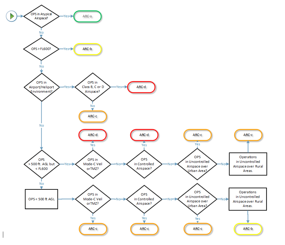
Figure 4 —
ARC assignment process
(d) The ARC is a qualitative classification of the rate at which a UAS would encounter a manned aircraft in typical generalised civil airspace. The ARC is an initial assignment of the aggregated collision risk for the airspace, before mitigations are applied. The actual collision risk of a specific local operational volume could be much different, and can be addressed with the application of strategic mitigations to reduce the ARC (this step is optional, see Section 2.4.3, Step #5).
(e) Although the static generalised risk put forward by the ARC is conservative (i.e. it stays on the safe side), there may be situations where that conservative assessment may not suffice. It is important for both the competent authority and the UAS operator to take great care to understand the operational volume and under which circumstances the definitions in Figure 4 could be invalidated. In some situations, the competent authority may raise the operational volume ARC to a level which is greater than that advocated by Figure 4. The ANSP should be consulted to ensure that the assumptions related to the operational volume are accurate.
(f) ARC-a is generally defined as airspace where the risk of a collision between a UAS and a manned aircraft is acceptable without the addition of any tactical mitigation.
(g) ARC-b, ARC-c, ARC-d generally define volumes of airspace with increasing risk of a collision between a UAS and a manned aircraft.
(h) During the UAS operation, the operational volume may span many different airspace environments. The applicant needs to perform an air risk assessment for the entire range of the operational volume. An example scenario of operations in multiple airspace environments is provided at the end of Annex C.
2.4.3 Step #5 — Application of strategic mitigations to determine the residual ARC (optional)
(a) As stated before, the ARC is a generalised qualitative classification of the rate at which a UAS would encounter a manned aircraft in the specific airspace environment. However, it is recognised that the UAS operational volume may have a different collision risk from the one that the generalised initial ARC assigned.
(b) If an applicant considers that the generalised initial ARC assigned is too high for the condition in the local operational volume, then they should refer to Annex C for the ARC reduction process.
(c) If the applicant considers that the generalised initial ARC assignment is correct for the condition in the local operational volume, then that ARC becomes the residual ARC.
2.4.4 Step #6 — TMPR and robustness levels
Tactical mitigations are applied to mitigate any residual risk of a mid-air collision that is needed to achieve the applicable airspace safety objective. Tactical mitigations will take the form of either ‘see and avoid’ (i.e. operations under VLOS), or they may require a system which provides an alternate means of achieving the applicable airspace safety objective (operation using a DAA, or multiple DAA systems). Annex D provides the method for applying tactical mitigations.
2.4.4.1 Operations under VLOS/EVLOS
(a) VLOS is considered to be an acceptable tactical mitigation for collision risk for all ARC levels. Notwithstanding the above, the UAS operator is advised to consider additional means to increase the situational awareness with regard to air traffic operating in the vicinity of the operational volume.
(b) Operational UAS flights under VLOS do not need to meet the TMPR, nor the TMPR robustness requirements. In the case of multiple segments of the flight, those segments conducted under VLOS do not have to meet the TMPR, nor the TMPR robustness requirements, whereas those conducted under BVLOS do need to meet the TMPR and the TMPR robustness requirements.
(c) In general, all VLOS requirements are applicable to EVLOS. EVLOS may have additional requirements over and above those of VLOS. The EVLOS verification and communication latency between the remote pilot and the observers should be less than 15 seconds.
(d) Notwithstanding the above, the applicant should have a documented VLOS de-confliction scheme, in which the applicant explains which methods will be used for detection, and defines the associated criteria applied for the decision to avoid incoming traffic. If the remote pilot relies on detection by observers, the use of phraseology will have to be described as well.
(e) For VLOS operations, it is assumed that an observer is not able to detect traffic beyond 2 NM. (Note that the 2 NM range is not a fixed value and it may largely depend on the atmospheric conditions, aircraft size, geometry, closing rate, etc.). Therefore, the UAS operator may have to adjust the operation and/or the procedures accordingly.
2.4.4.2 Operations under a DAA system — TMPR
(a) For operations other than VLOS, the applicant will use the residual ARC and Table 4 below to determine the TMPR.
|
Residual ARC |
TMPRs |
TMPR level of robustness |
|
ARC-d |
High |
High |
|
ARC-c |
Medium |
Medium |
|
ARC-b |
Low |
Low |
|
ARC-a |
No requirement |
No requirement |
Table 4 —
TMPRs and TMPR level of robustness assignment
(b) High TMPR (ARC-d): This is airspace where either the manned aircraft encounter rate is high, and/or the available strategic mitigations are low. Therefore, the resulting residual collision risk is high, and the TMPR is also high. In this airspace, the UAS may be operating in integrated airspace and will have to comply with the operating rules and procedures applicable to that airspace, without reducing the existing capacity, decreasing safety, negatively impacting current operations with manned aircraft, or increasing the risk to airspace users or persons and property on the ground. This is no different from the requirements for the integration of comparable new and novel technologies in manned aviation. The performance level(s) of those tactical mitigations and/or the required variety of tactical mitigations are generally higher than for the other ARCs. If operations in this airspace are conducted more routinely, the competent authority is expected to require the UAS operator to comply with the recognised DAA system standards (e.g. those developed by RTCA SC-228 and/or EUROCAE WG-105).
(c) Medium TMPR (ARC-c): A medium TMPR will be required for operations in airspace where the chance of encountering manned aircraft is reasonable, and/or the strategic mitigations available are medium. Operations with a medium TMPR will likely be supported by the systems currently used in aviation to aid the remote pilot in the detection of other manned aircraft, or by systems designed to support aviation that are built to a corresponding level of robustness. Traffic avoidance manoeuvres could be more advanced than for a low TMPR.
(d) Low TMPR (ARC-b): A low TMPR will be required for operations in airspace where the probability of encountering another manned aircraft is low, but not negligible, and/or where strategic mitigations address most of the risk, and the resulting residual collision risk is low. Operations with a low TMPR are supported by technology that is designed to aid the remote pilot in detecting other traffic, but which may be built to lower standards. For example, for operations below 120 m, the traffic avoidance manoeuvres are expected to mostly be based on a rapid descent to an altitude where manned aircraft are not expected to ever operate.
(e) No performance requirement (ARC-a): This is airspace where the manned aircraft encounter rate is expected to be extremely low, and therefore there is no requirement for a TMPR. It is generally defined as airspace where the risk of a collision between a UAS and a manned aircraft is acceptable without the addition of any tactical mitigation. An example of this may be UAS flight operations in some parts of Alaska or northern Sweden, where the manned aircraft density is so low that the airspace safety threshold could be met without any tactical mitigation.
(f) Annex D provides information on how to satisfy the TMPR based on the available tactical mitigations and the TMPR level of robustness.
2.4.4.3 Consideration of additional airspace/operational requirements
(a) Modifications to the initial and subsequent approvals may be required by the competent authority or the ANSP as safety and operational issues arise.
(b) The UAS operator and the competent authority need to be cognisant that the ARCs are a generalised qualitative classification of the collision risk. Local circumstances could invalidate the aircraft density assumptions of the SORA, for example, due to special events. It is important for both the competent authority and the UAS operator to fully understand the airspace and air‑traffic flows, and develop a system which can alert UAS operators to changes to the airspace on a local level. This will allow the UAS operator to safely address the increased risks associated with these events.
(c) There are many airspace, operational and equipment requirements which have a direct impact on the collision risk of all aircraft in the airspace. Some of these requirements are general and apply to all volumes of airspace, while some are local and are required only for a particular volume of airspace. The SORA cannot possibly cover all the possible requirements for all the conditions in which the UAS operator may wish to operate. The applicant and the competent authority need to work closely together to define and address these additional requirements.
(d) The SORA process should not be used to support operations of a UAS in a given airspace without the UAS being equipped with the required equipment for operations in that airspace (e.g. the equipment required to ensure interoperability with other airspace users). In these cases, specific exemptions may be granted by the competent authority. Those exemptions are outside the scope of the SORA.
(e) Operations in controlled airspace, an airport/heliport environment or a Mode-C Veil/transponder mandatory zone (TMZ) will likely require prior approval from the ANSP. The applicant should ensure that they involve the ANSP/authority prior to commencing operations in these environments.
2.5 Final assignment of specific assurance and integrity level (SAIL) and OSO
2.5.1 Step #7 SAIL determination
(a) The SAIL parameter consolidates the ground and air risk analyses, and drives the required activities. The SAIL represents the level of confidence that the UAS operation will remain under control.
(b) After determining the final GRC and the residual ARC, it is then possible to derive the SAIL associated with the proposed ConOps.
(c) The level of confidence that the operation will remain under control is represented by the SAIL. The SAIL is not quantitative, but instead corresponds to:
(1) the OSO to be complied with (see Table 6);
(2) the description of the activities that might support compliance with those objectives; and
(3) the evidence that indicates that the objectives have been satisfied.
(d) The SAIL assigned to a particular ConOps is determined using Table 5:
|
SAIL
determination |
||||
|
|
Residual ARC |
|||
|
Final GRC |
a |
b |
c |
d |
|
≤2 |
I |
II |
IV |
VI |
|
3 |
II |
II |
IV |
VI |
|
4 |
III |
III |
IV |
VI |
|
5 |
IV |
IV |
IV |
VI |
|
6 |
V |
V |
V |
VI |
|
7 |
VI |
VI |
VI |
VI |
|
>7 |
Category C operation |
|||
Table
5 — SAIL determination
2.5.2 Step #8 — Identification of the operational safety objectives (OSOs)
(a) The last step of the SORA process is to use the SAIL to evaluate the defences within the operation in the form of OSOs, and to determine the associated level of robustness. Table 6 provides a qualitative methodology to make this determination. In this table, O is optional, L is recommended with low robustness, M is recommended with medium robustness, and H is recommended with high robustness. The various OSOs are grouped based on the threat they help to mitigate; hence, some OSOs may be repeated in the table.
(b) Table 6 is a consolidated list of the common OSOs that historically have been used to ensure safe UAS operations. It represents the collected experience of many experts, and is therefore a solid starting point to determine the required safety objectives for a specific operation. The competent authorities that issue the operational authorisation may define additional OSOs for a given SAIL and the associated level of robustness.
|
OSO number (in
line with Annex E) |
|
SAIL |
|||||
|
I |
II |
III |
IV |
V |
VI |
||
|
|
Technical issue with the UAS |
|
|
|
|
|
|
|
OSO#01 |
Ensure the UAS operator is competent and/or proven |
O |
L |
M |
H |
H |
H |
|
OSO#02 |
UAS manufactured by competent and/or proven entity |
O |
O |
L |
M |
H |
H |
|
OSO#03 |
UAS maintained by competent and/or proven entity |
L |
L |
M |
M |
H |
H |
|
OSO#04 |
UAS developed to authority recognised design standards[27] |
O |
O |
O |
L |
M |
H |
|
OSO#05 |
UAS is designed considering system safety and reliability |
O |
O |
L |
M |
H |
H |
|
OSO#06 |
C3 link performance is appropriate for the operation |
O |
L |
L |
M |
H |
H |
|
OSO#07 |
Inspection of the UAS (product inspection) to ensure consistency with the ConOps |
L |
L |
M |
M |
H |
H |
|
OSO#08 |
Operational procedures are defined, validated and adhered to |
L |
M |
H |
H |
H |
H |
|
OSO#09 |
Remote crew trained and current and able to control the abnormal situation |
L |
L |
M |
M |
H |
H |
|
OSO#10 |
Safe recovery from a technical issue |
L |
L |
M |
M |
H |
H |
|
|
Deterioration of external systems supporting UAS operations |
|
|
|
|
|
|
|
OSO#11 |
Procedures are in-place to handle the deterioration of external systems supporting UAS operations |
L |
M |
H |
H |
H |
H |
|
OSO#12 |
The UAS is designed to manage the deterioration of external systems supporting UAS operations |
L |
L |
M |
M |
H |
H |
|
OSO#13 |
External services supporting UAS operations are adequate for the operation |
L |
L |
M |
H |
H |
H |
|
|
Human error |
|
|
|
|
|
|
|
OSO#14 |
Operational procedures are defined, validated and adhered to |
L |
M |
H |
H |
H |
H |
|
OSO#15 |
Remote crew trained and current and able to control the abnormal situation |
L |
L |
M |
M |
H |
H |
|
OSO#16 |
Multi-crew coordination |
L |
L |
M |
M |
H |
H |
|
OSO#17 |
Remote crew is fit to operate |
L |
L |
M |
M |
H |
H |
|
OSO#18 |
Automatic protection of the flight envelope from human error |
O |
O |
L |
M |
H |
H |
|
OSO#19 |
Safe recovery from human error |
O |
O |
L |
M |
M |
H |
|
OSO#20 |
A human factors evaluation has been performed and the human machine interface (HMI) found appropriate for the mission |
O |
L |
L |
M |
M |
H |
|
|
Adverse operating conditions |
|
|
|
|
|
|
|
OSO#21 |
Operational procedures are defined, validated and adhered to |
L |
M |
H |
H |
H |
H |
|
OSO#22 |
The remote crew is trained to identify critical environmental conditions and to avoid them |
L |
L |
M |
M |
M |
H |
|
OSO#23 |
Environmental conditions for safe operations are defined, measurable and adhered to |
L |
L |
M |
M |
H |
H |
|
OSO#24 |
UAS is designed and qualified for adverse environmental conditions |
O |
O |
M |
H |
H |
H |
Table
6 — Recommended OSOs
2.5.3 Step #9 – Adjacent area/airspace considerations
(a) The objective of this section is to address the risk posed by a loss of control of the operation, resulting in an infringement of the adjacent areas on the ground and/or adjacent airspace. These areas may vary with different flight phases.
(b) Safety requirements for ‘basic containment’ are:
|
No probable[28] failure[29] of the UAS or any external system supporting the operation should lead to operation outside the operational volume. Compliance with the requirement above should
be substantiated by a design and installation appraisal and should include
at least: —
the design and
installation features (independence, separation and redundancy); Note: Independence, separation and
redundancy are not necessarily required, but they may be useful to
substantiate the robustness of the containment system. —
any relevant
particular risk (e.g. hail, ice, snow, electromagnetic interference, etc.)
associated with the ConOps. The competent authority may accept a declaration for the claimed integrity. The applicant declares that the required level of integrity has been achieved and supporting evidence is available. |
(c) The enhanced containment applies to operations conducted:
(1) either where the adjacent areas:
(i) contain assemblies of people[30] unless the UAS is already approved for operations over assemblies of people; or
(ii) are ARC-d unless the residual ARC of the airspace area intended to be flown within the operational volume is already ARC-d;
(2) Or where the operational volume is in a populated area where:
(i) M1 mitigation has been applied to lower the GRC; or
(ii) operating in a controlled ground area.
(d) The enhanced containment consists in the following safety requirements:
|
(a) The UAS is designed to standards that are considered adequate by the competent authority and/or in accordance with a means of compliance that is acceptable to that authority such that: (1) the probability of the UA leaving the operational volume should be less than 10‑4/FH; and (2) no single failure* of the UAS or any external system supporting the operation should lead to its operation outside the ground risk buffer. Compliance with the requirements above should be substantiated by analysis and/or test data with supporting evidence. (b) Software (SW) and airborne electronic hardware (AEH) whose development error(s) could directly (refer to Note 2) lead to operations outside the ground risk buffer should be developed to an industry standard or methodology that is recognised as being adequate by EASA. |
For UA with maximum characteristic dimensions not greater than 3 m, operated up to SAIL II operations, the competent authority may accept a declaration from the applicant for the compliance with the MoC to Light-UAS.2511[31]. For UAS configurations exceeding the applicability of such MoC[32], the competent authority may decide to still accept declarations based on such MoC with evidence available, or to accept appropriate MoC proposed by the applicant. Otherwise, the competent authority may request the applicant to use a UAS for which EASA has verified the claimed integrity.
As it is not possible to anticipate all local situations, the UAS operator, the competent authority and the ANSP should use sound judgement with regard to the definition of the ‘adjacent airspace’ as well as the ‘adjacent areas’. For example, for a small UAS with a limited range, these definitions are not intended to include busy airport/heliport environments 30 kilometres away. The airspace bordering the UAS volume of operation should be the starting point of the determination of the adjacent airspace. In exceptional cases, the airspace beyond those volumes that border the UAS volume of operation may also have to be considered.
Note 1: The safety requirements as proposed in this section cover both the integrity and assurance levels.
Note 2: The third safety requirement in Section 2.5.3(c) does not imply a systematic need to develop the SW and AEH according to an industry standard or methodology recognised as adequate by the competent authority. The use of the term ‘directly’ means that a development error in a software or an airborne electronic hardware would lead the UA outside the ground risk buffer without the possibility for another system to prevent the UA from exiting the operational volume.
2.6 Step #10 — comprehensive safety portfolio
(a) The SORA process provides the applicant, the competent authority and the ANSP with a methodology which includes a series of mitigations and safety objectives to be considered to ensure an adequate level of confidence that the operation can be safely conducted. These are:
(1) mitigations used to modify the intrinsic GRC;
(2) strategic mitigations for the initial ARC;
(3) tactical mitigations for the residual ARC;
(4) adjacent area/airspace considerations; and
(5) OSOs.
(b) The satisfactory substantiation of the mitigations and objectives required by the SORA process provides a sufficient level of confidence that the proposed operation can be safely conducted.
(c) The UAS operator should be sure to address any additional requirements that were not identified by the SORA process (e.g. for security, environmental protection, etc.) and identify the relevant stakeholders (e.g. environmental protection agencies, national security bodies, etc.). The activities performed within the SORA process will likely address those additional needs, but they may not be considered to be sufficient at all times.
(d) The UAS operator should ensure the consistency between the SORA safety case and the actual operational conditions (i.e. at the time of the flight).
[15] https://www.easa.europa.eu/sites/default/files/dfu/guidelines_design_verification_uas_medium_risk.pdf
[19] If the UAS has a DVR covering the full design, this may cover also the mitigation means.
[20] The flight technical error is the error between the actual track and the desired track (sometimes referred to as ‘the ability to fly the flight director’).
[22] In line with Figure 1 and point 2.3.1(c), the controlled area should encompass the flight geography, the contingency volume, and the ground risk buffer.
[23] EVLOS — A UAS operation whereby the remote pilot maintains uninterrupted situational awareness of the airspace in which the UAS operation is being conducted via visual airspace surveillance through one or more human VOs, possibly aided by technological means. The remote pilot has direct control of the UAS at all times.
[25] This mitigation is meant as a means to reduce the number of people at risk.
[26] This mitigation is meant as a means to reduce the energy absorbed by the people on the ground upon impact.
[27] In
the case of experimental flights that investigate new technical solutions, the
competent authority may accept that recognised standards are not met.
[28] The term ‘probable’ needs to be understood in its qualitative interpretation, i.e. ‘Anticipated to occur one or more times during the entire system/operational life of an item.’
[29] The term ‘failure’ needs to be understood as an occurrence that affects the operation of a component, part, or element such that it can no longer function as intended. Errors may cause failures, but are not considered to be failures. Some structural or mechanical failures may be excluded from the criterion if it can be shown that these mechanical parts were designed according to aviation industry best practices.
* The term ‘failure’ needs to be understood as an occurrence that affects the operation of a component, part, or element such that it can no longer function as intended. Errors may cause failures, but are not considered to be failures. Some structural or mechanical failures may be excluded from the criterion if it can be shown that these mechanical parts were designed according to aviation industry best practices.